Sometime last year some friends approached me about a project they were working on and maybe wanted me to get involved with. While this didnt lead anywhere one of the concepts we were discussing really intrigued me and I wanted to have ago, seeing it as a fun little challenge.
But with other projects in the pipeline I didnt really manage to find the time to do it...
My youtube channel had started to get a bit of a boost in popularity and I thought about doing some prep for this project and put it on the back burner. The idea was to make this as a special project to celebrate passing 1000 subscribers.
Well this last couple of weeks that happened. So I've pushed ahead with getting this project finished, and as a celebration, I'm realising all the source files for this project free to use under simple CC-NC agreement.
So feel free to download order a bunch of pcbs and build your own set of digits, just dont go selling them on tindie or anywhere else, or I'll bite!
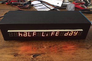
Each digit has its own 595 shift register, and solder connections on the side. The idea is that each digit can be placed side by side and small hoops of wire could be used to secure each digit.
In theory these digits could run for many maybe over 100 connections. But power supply needs to be taken into consideration.
The digits use a matrix of 4x4 leds. Thats 4 rows of 4 LEDs. (though these are grouped in quarters of the square) with a resistor of 150 ohms these LEDs max current draw is 15ma per led, though calculates to roughly 13ma.
As the LEDs are driven row by row in a 4 row interlaced signal that gives each digit a maximum draw of around 60ma. if the LEDs were being driven at full brightness, and if the arduino code was behaving and not trigger multiple rows at the same time.
There is also a PWM signal that can control the brightness, and Ive found on the 8bit arduino PWM control, the value of 50 is plenty.
But some consideration should be made to the power supply, both on the 5V and ground. With multiple re connections to power for long chains. For example, my subscriber counter I made using these digits, has 15 digits. And i connected the power to both ends of the chain to help take stress off the power traces.
I originally planned to have an ESP8266 drive the digits directly. But I found this to be impossible with the hardware available in the micro controller. So in the end I made a dedicated controller with an Arduino pro mini (atmega328p). And created a serial interface setup that allowed me to feed data to the display from the ESP8266.
The Arduino drives the display constantly by regular hardware timer intervals of 500ns, using the built in SPI hardware to shift out the data at a more than fast rate. At this constant rate with the 4 row interlace, I'm getting perfectly flicker free image persistence. in fact the data update rate is far faster than I had originally envisioned.
I also needed to manufacture the face plate defusers for the digits. I considered making the face plates with my resin printer. And this indeed may have worked out well. But in the end i went with using my laser cutter in engrave mode. And engraving into black perspex to route out spaces for the components before another engrave pass for the small 3 dot holes for each segment of the display. This took a lot of trial and error but in the end I got a fairly decent result.
I then used clear UV curable resin to fill up the holes, using a sowing needle to paste the liquid over them, and after curing them sanded the faces flat again leaving a matt clean finish. I also gave the faces a spray with plasticote matt finish to give them a more uniform look. This worked out really well.
But the defusing effect isn't perfectly consistent with each segment and each digit. With more practice and homing in on the technique this could be improved but, i got a good enough result for the project I wanted at this time.
At the...
Read more » Mangus Tiranus


 Atheros
 JF
JF

 Mark VandeWettering
Is this spam?