T1 Specifications:
- 28.4n/m theoretical output torque
- 43.3n/m tested gearbox yield toque
- 45:1
- 24v
- 543g
Thermal Management:
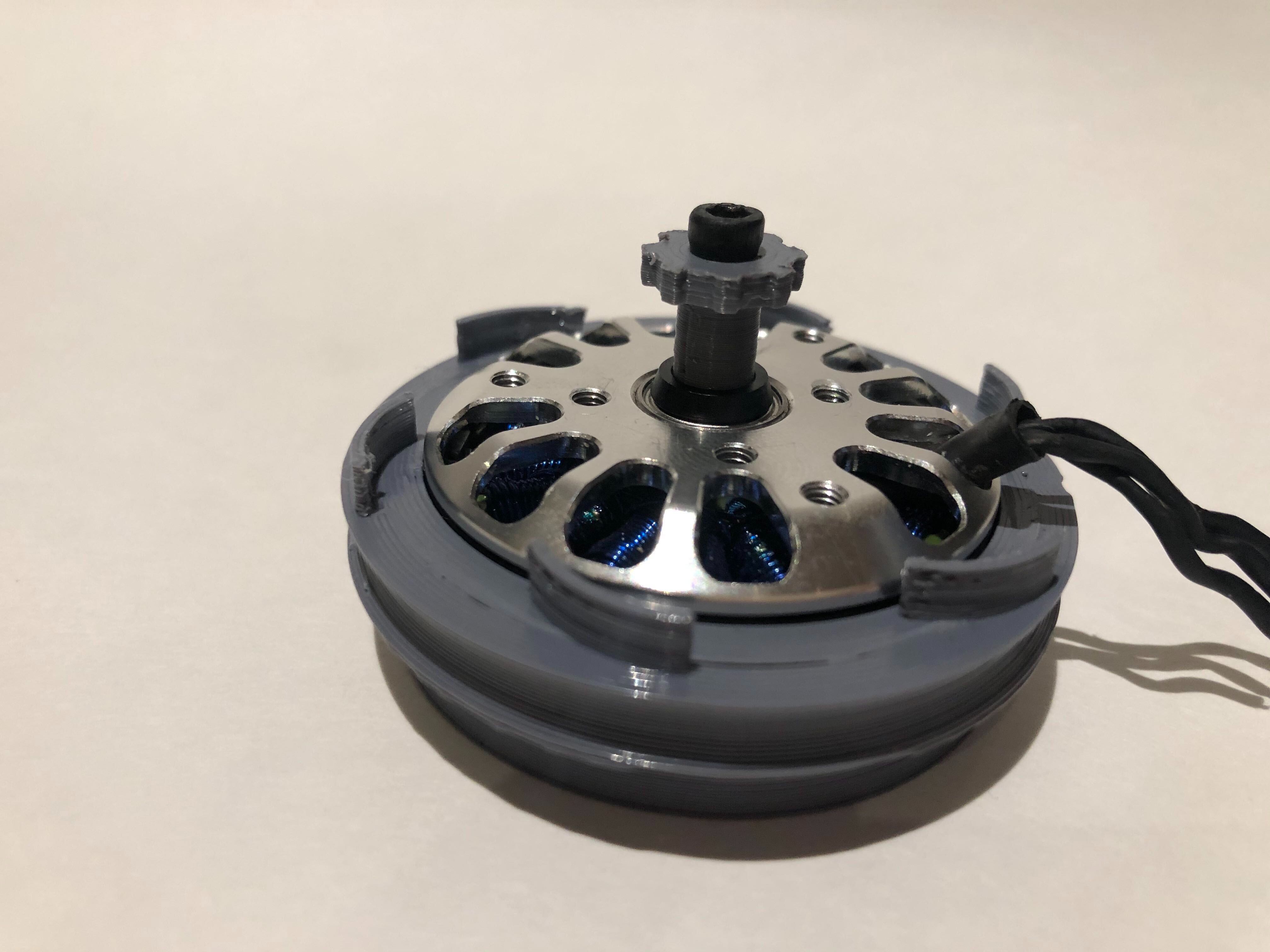
The gearbox produces heat, from friction on the teeth and in the elliptical bearing, as well as from the motor and electronics. Unfortunately, the very fact that FDM printing works through thermal extrusion limits us to materials with relatively low glass transition temperatures. Further, to avoid contamination, we would prefer to have no external vents. We have noticed deformation under thermal load on several prototypes. With that in mind, our current prototype has fan blades on the wave generator, as well as ducts to allow airflow within the gearbox.

The spline pictured above interfaces with the 8192 CPR encoder through a hole in the shell
Filament Choice:
After some research online, we chose to print with IC3D PETG for its high layer adhesion and low shrinkage (important for gear interface). However, in comparison to prior prints in ABS and PLA, its high density surprised us. After prototyping, we are considering swapping to Polycarbonate for its higher glass transition temperature, lower density, and ability to withstand higher torsional stresses. Unfortunately, PC’s high shrinkage tendencies may pose an issue. If you have any recommendations please let me know, I'm all ears!
Lubricant choice:
PTFE was used between the wave generator, ball-cage, ball bearings, and flex spline because a few airsofting forums suggested it was the best choice for the PETG gearboxes in their rifles. If anyone has more experience with this, I’d love to hear it.
Tooth Kinematics:
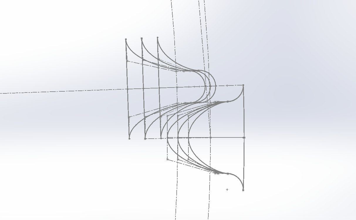
As a result of the unique relative motion profile between the fixed and flex spline, we used Matlab to design a custom tooth shape to improve engagement characteristics and increase load capacity. An expired patent explains a similar approach.

Manufacturing: (Lulzbot Taz 6 & CuraLulzbot 3.6.2)
We 3D printed every part possible, including the ball cage and the lower elliptical bearing. We are currently designing a method to make the output bearing in the same fashion in the future.
Print settings were optimized for each part and custom profiles for each are linked below. Note: this is what has worked best for us, your printer may be different. We started with priority on surface quality but soon realized that structural properties were far more important. Z seams on bearing surfaces, layer adhesion, and print direction had much more of an effect on the function of the gearbox. Notable changes include a tweakAtZ in print speed from 60mm/s to 20mm/s during the layers with teeth, infill overlap percentage reduction (100% infill led to material buildup and artifacting), retraction tuning (the precise ball cage is an intense test), and support parameter changes. If you have any questions about printing profiles, message me - I’d love to help!
We are open to collaboration or employment opportunities.
 Cameron

can you share step file ?