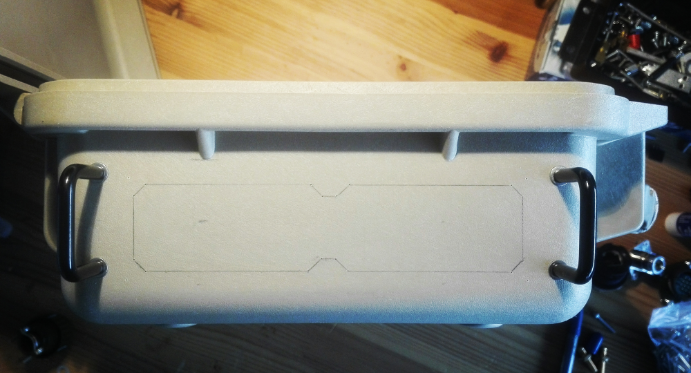
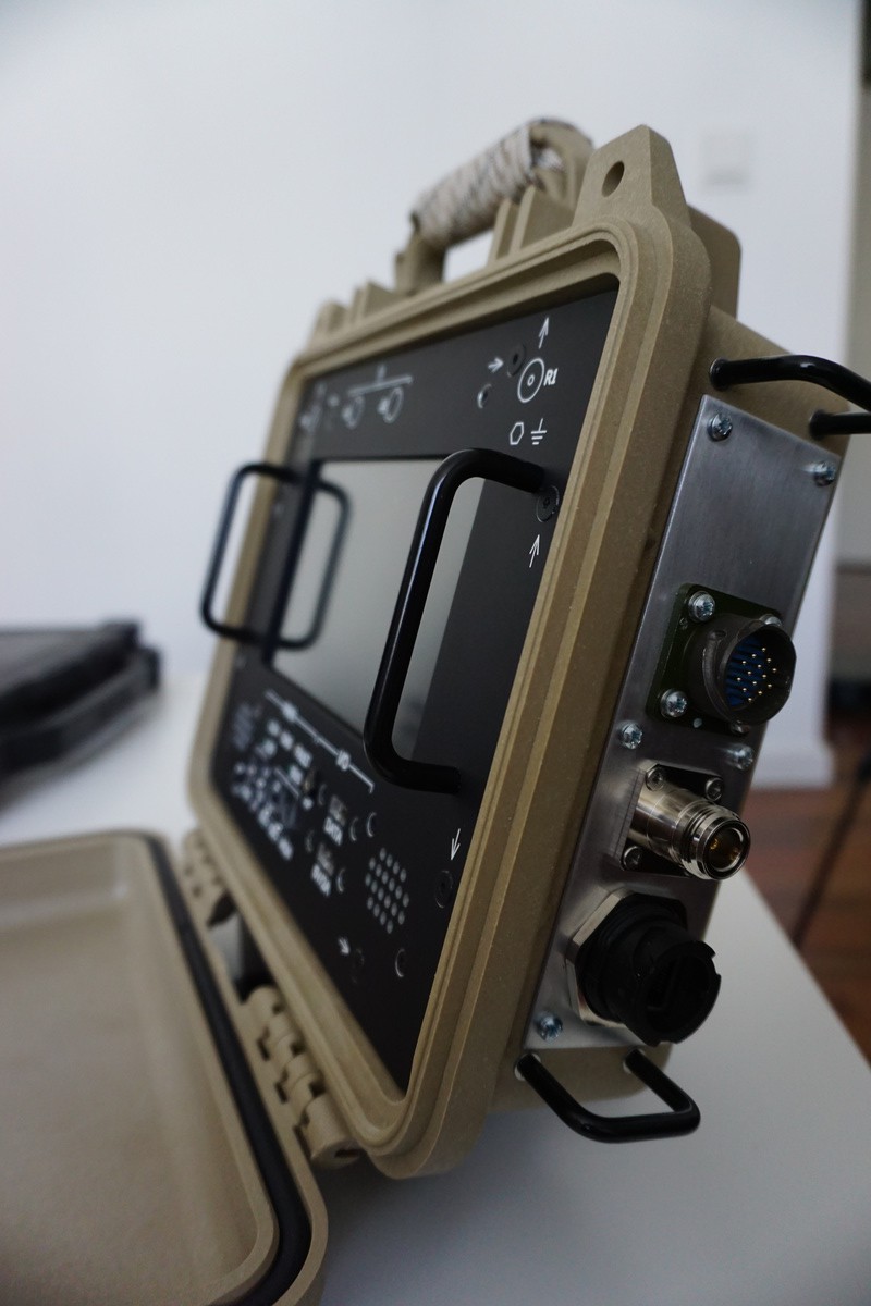
The last part of the integration consisted of the addition of the side interfacing panel - containing network connection, power and external GPS antenna connector. Early on in the design process, it was chosen to not put these interfaces on the front user panel, as the network and power interface need to be accessible when the unit is closed when operated in remote mode for example.

2 handles (Hammond mfg 1427B2BK) normally used for rack modules were used as connector protection rails if the unit is placed on the respective side. The connectors are mounted in a 2mm thick aluminium plate which is in turn bolted to the case after a back-supporting section was cut out. This has the advantage that another plate with different connectors could still be placed afterwards, or other connectors added, and not needing any modifications of the case itself.
Finished panel showing the RJ45, GPS antenna and Power connector:

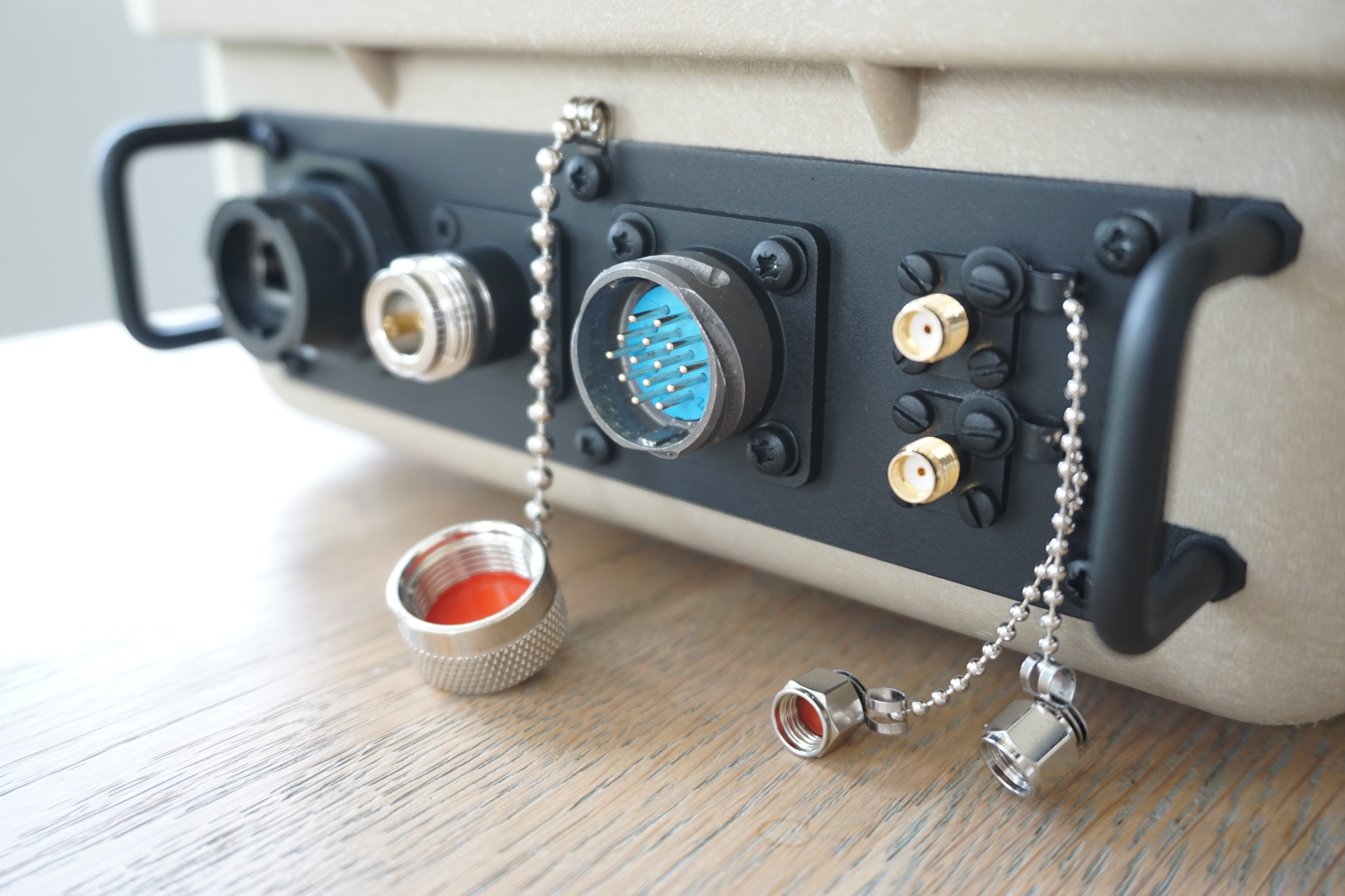
The finished patchpanel is shown below.
Connectors from left to right:
- Ethernet
- N-connector (for external GPS antenna)
- Multipurpose 14-pin PWR + IO
- 2x SMA (WLAN + auxiliary RF feedthrough)

 Tom Mladenov
Discussions
Become a Hackaday.io Member
Create an account to leave a comment. Already have an account? Log In.