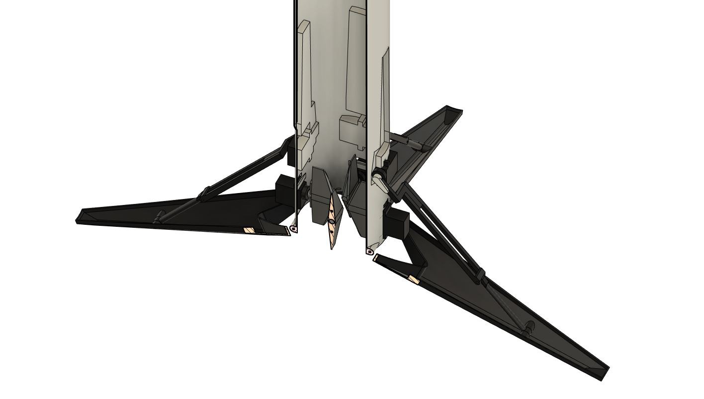
As mentioned above I decided to go for the Falcon 9 look but had to make some adjustments to turn this rocket into a functional one. The landing legs for example look very similar than the Falcon 9 booster landing legs but use a completely different way to deploy and retract them, simply because of the smaller scale i have to work with. I used standard 9g hobby servo's and designed a hinge mechanism to deploy and retract the legs, this means i had to make some cutouts in the body of the rocket in order for the legs to fold down nicely against the body of the rocket. All the legs are designed to lock in place once fully extended so there is no torque applied to the servos when the landing gear is under load, the forces of the landing gear are in line with the shaft of the servos once they are fully extended.
Update 09-12-2020: after doing some more testing the landing gear seems to be not as durable as i would like it to be. I had to replace some servo's and a few 3D-printed arms broke during hard landings. I'm now looking into changing the servo's out for a small pneumatic system on the next version of this rocket. For now I'll just keep the landing gear fixed so i can proceed the testing with the current prototype.
STL and Fusion 360 source files can be found here: https://bbprojects.technology/collections/stl-fusion-360-source-files/products/spacex-inspired-edf-rocket-model
The design and build video of the original landing leg system (using servo's) can be found here:
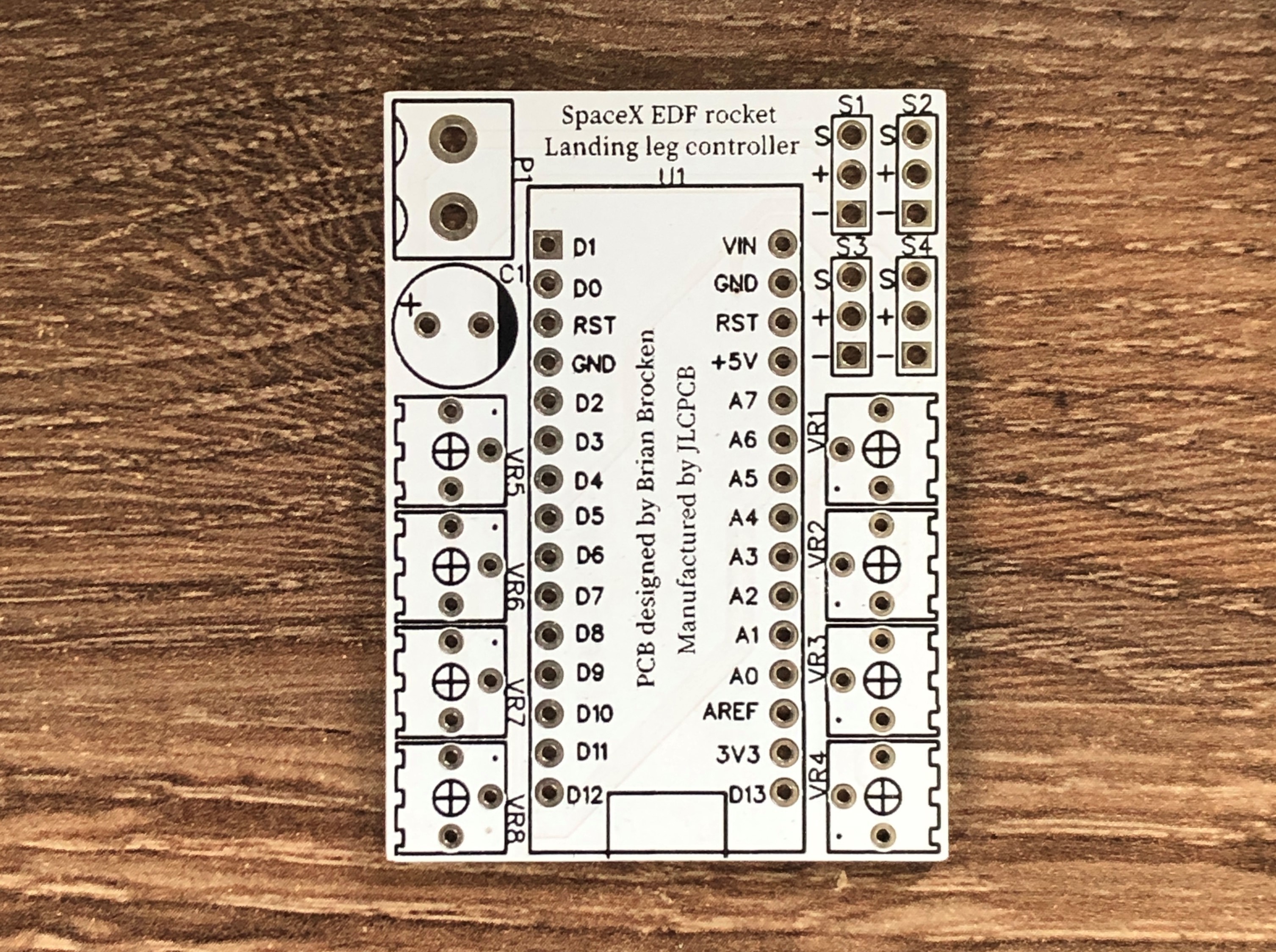
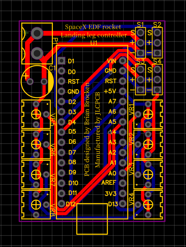
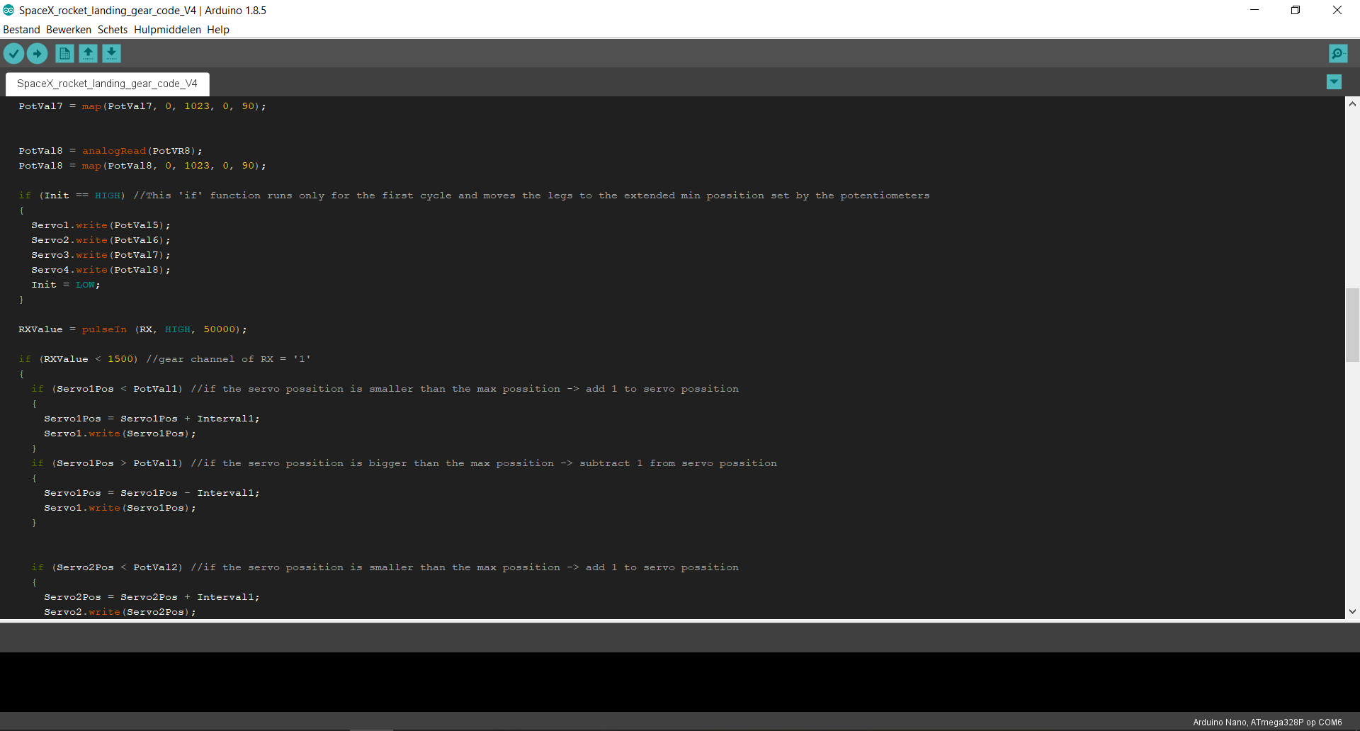
To control the speed of the landing legs and setup the max and min possitions for each leg I decided to create a small Arduino based PCB which was manufactured by JLCPCB, the sponsor of this project. The gerber files and Arduino code can be found in the files section of this project page.
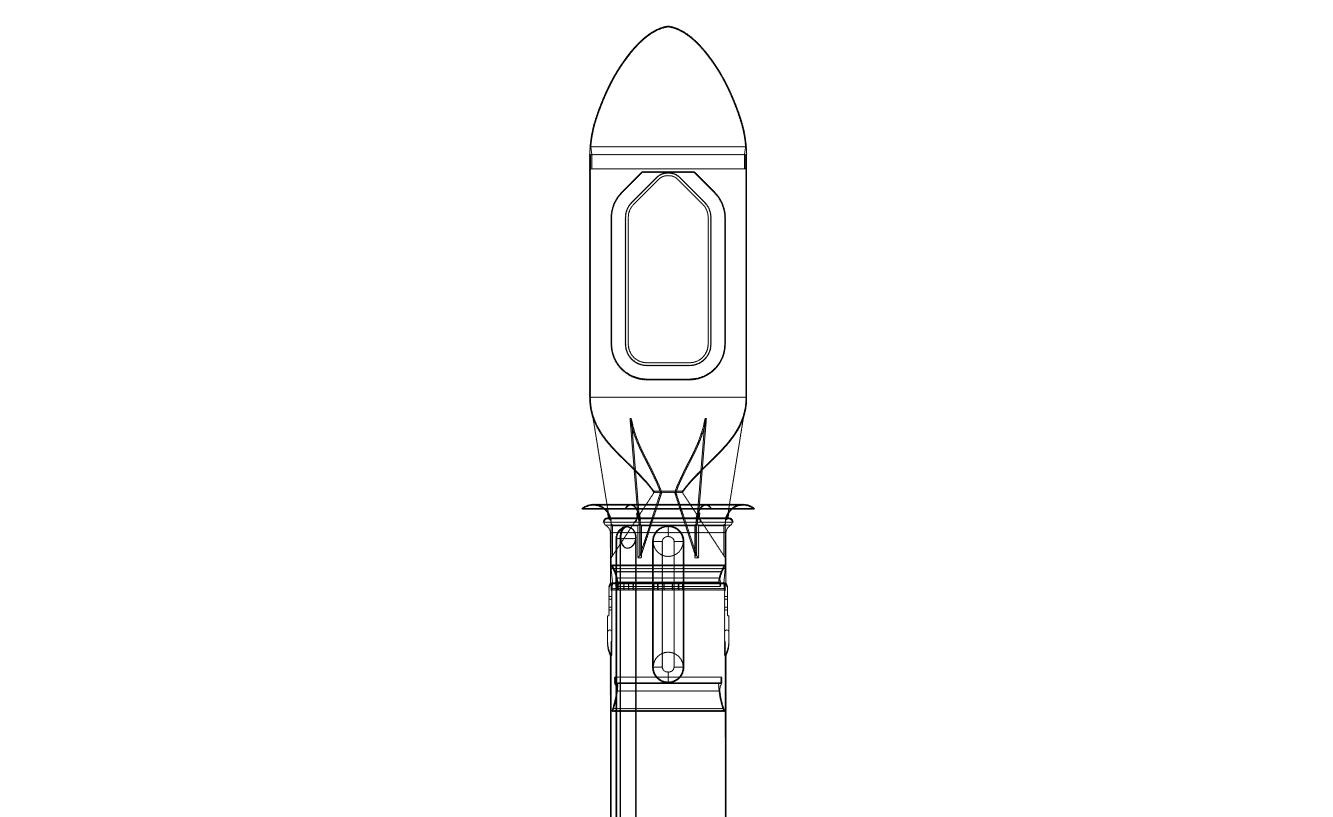
I used a 6s 70mm 12 blade 2300kv electric ducted fan as thrust unit. This means I have to implement air inlets on top of the rocket, just beneath the nose/payload area of the rocket. The inside of the rocket needs to be as clean as possible in order for the air inside to flow uninterupted. So I decided to move all the signal and power cables, that run from the top of the rocket to the bottom, on the outside in a channel, this way there are no lose wires inside the body where the air needs to flow.
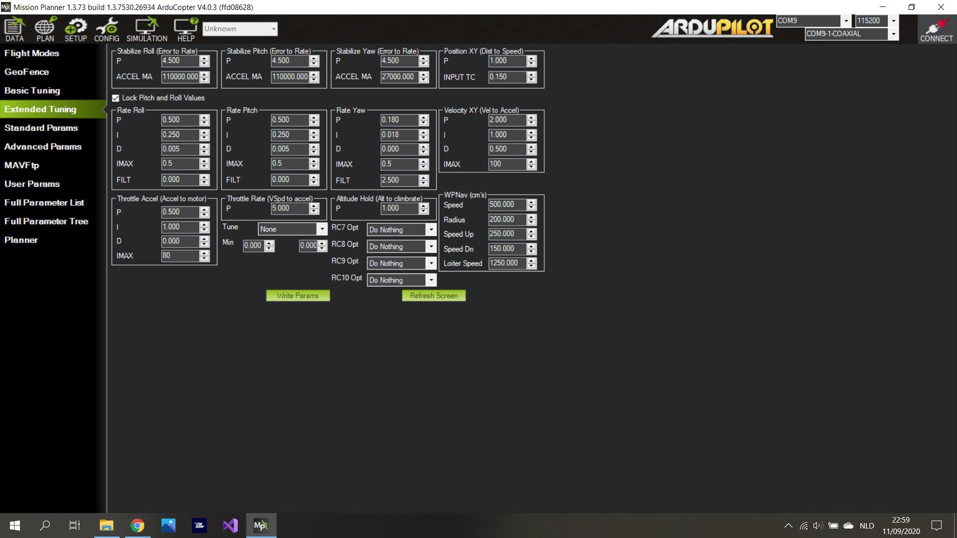
On the bottom side of the rocket there are 4 fins that control the direction of the air that's coming from the EDF unit. This in combination with the throttle control of the EDF enables the rocket to have 4 axis of control. These 4 fins, the thrust vector control unit, are being controlled by a Pixhawk PX4 flight controller running ardupilot that's configured as a single copter.
All the parts are designed using Autodesk Fusion 360, and are all printed with my Anet E12 and reprap prusa I3.
The maiden flight can be seen here:
 Brian Brocken



 Sagar
Sagar
 Jackson Miller
 Benjamin Prescher
 Nick Rehm
Amazing job! Which firmware version are you use, Arduplane or Arducopter? and how these 4 servor functons configed in firmware?