 Matthew James Bellafaire
Well we now have RGB LEDs in the mix, to add another splash of color to the design. For the most part the addition of the LEDs was to add more complexity to the wiring and make the entire build feel more complete. In total the LEDs constitute another 8 wires that needed to be run. I ended up breaking from the original schematic just because there were other pins that were more available than the ones I originally picked. In its current state the project is taking shape:
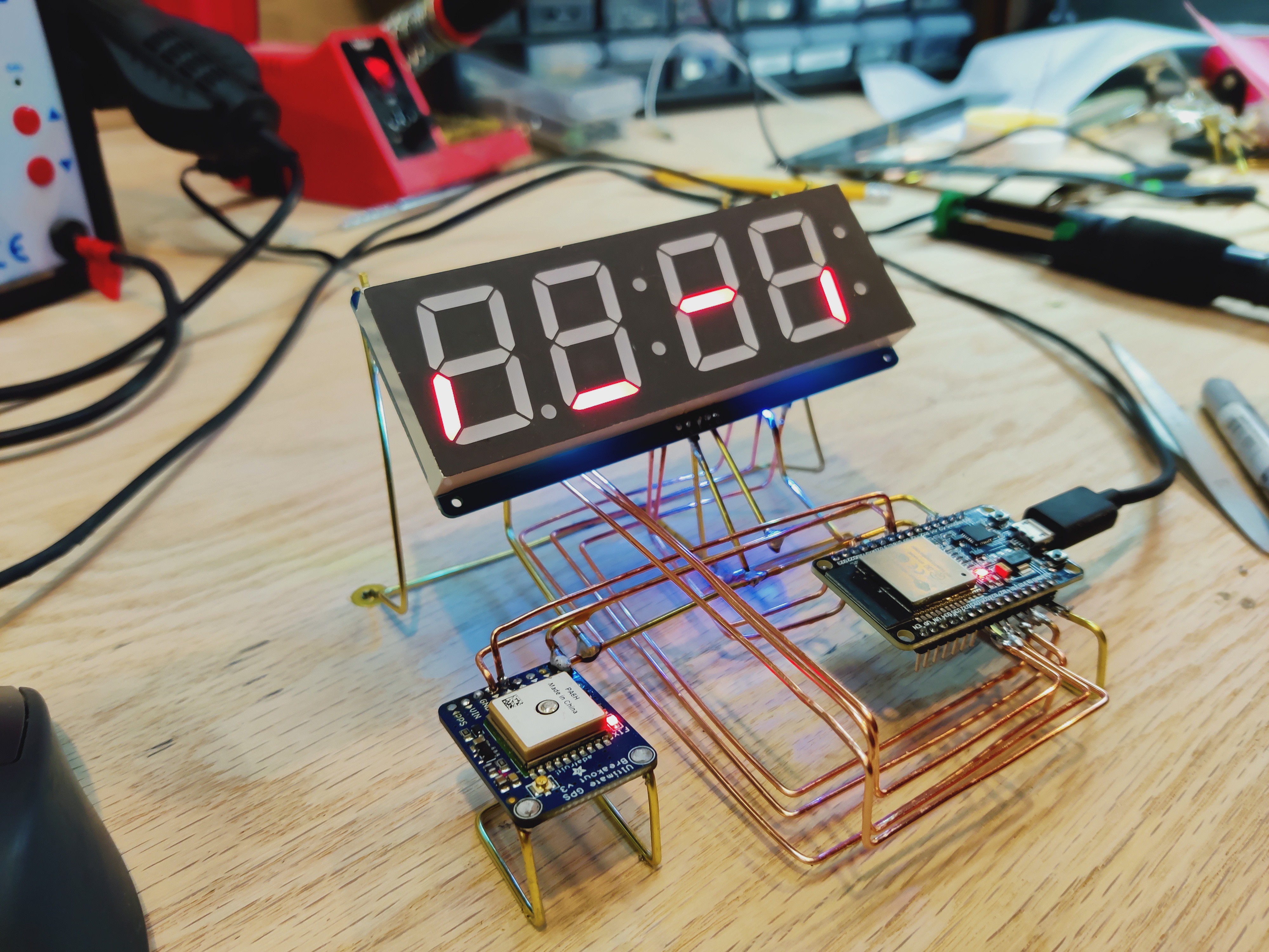
the RGB LEDs are tucked up under the seven segment and just point up to give some diffuse underlighting, the backside isn't nearly as pretty but nobody really needs to see it. I ended up neglecting the 220-ohm resistors, mostly because I don't have any resistors that that have structurally strong leads. This project falls firmly under the "for the fun of it" category so I'm not going to stress the details too much.
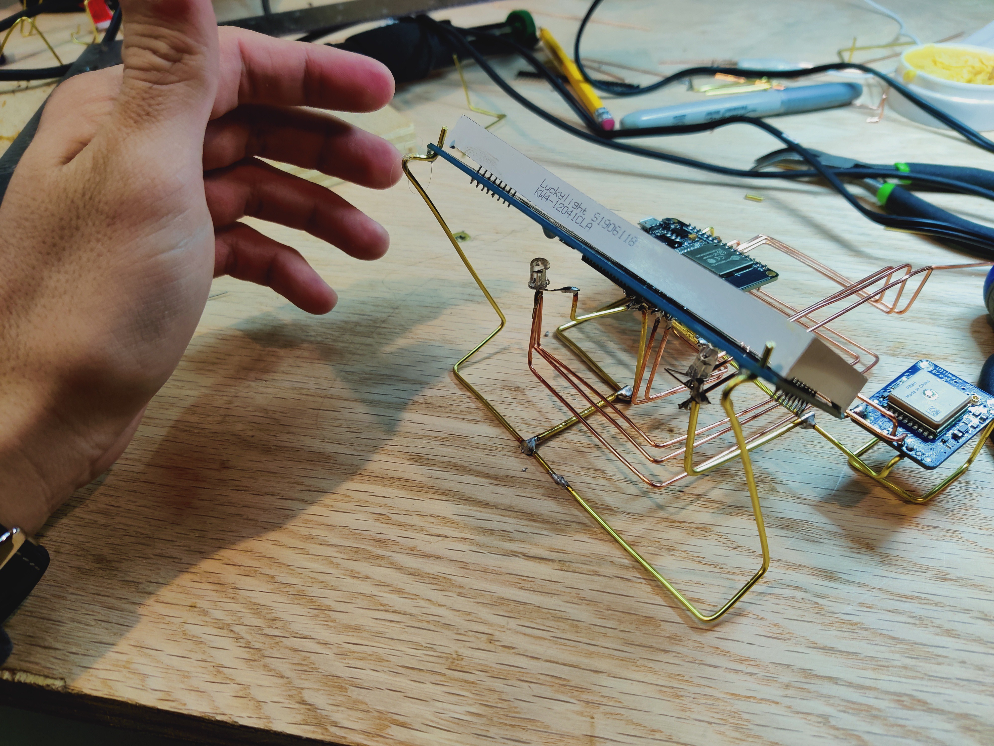
I also reworked the structure a bit so that the seven seg is supported by some wire. Either way here's the clock in its current state with some simple test code:
Unfortunately, I didn't make it to the point of being able to put in the photoresistor or the buttons (might skip the buttons and just put everything in firmware).
Discussions
Become a Hackaday.io Member
Create an account to leave a comment. Already have an account? Log In.