 Paul McClay
Continuing the log catch-up campaign...
Earlier I mentioned keeping all the AC power wiring in the top of the frame, with intent to include a logic-switched power outlet for the "spindle".
I'm going to mostly skip a couple iterations of "improving" that because:
- it will expedite the log catch-up campaign, and
- I'm not an electrician and sometimes do dumber stuff than usual that's easier to pretend didn't happen if I don't write Log pages about it.
I did manage a first whack at fitting logic switched spindle power inside the box, so here's a few pix.
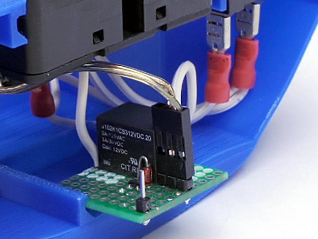
Relay in the hot wire to a 1-15R outlet (the usual US two-prong polarized -- because that's the plug on my US market dremeloid).
12VDC supply for the relay coil.
Header pin for the "spindle enable" signal.
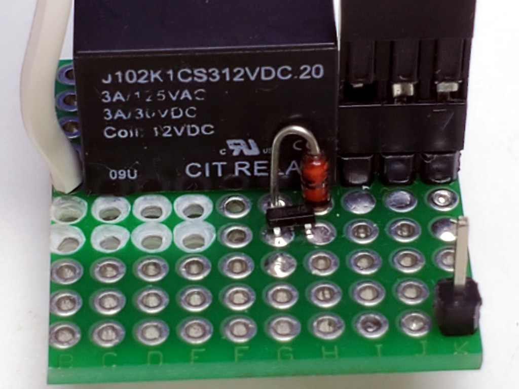
Signal pin and FET for switching coil power (coil supply ground is common with the controller).
Flyback diode because conventional wisdom says "flyback diode" -- no math attempted.
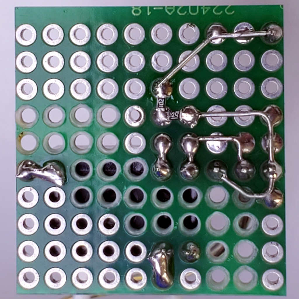
Plated thru-holes de-plated for HV/LV isolation.
Resistors under the FET: gate pulldown and a "protection" resistor because resistors between stuff and off-board connections make me feel gooder. Am not EE.
Using a 3 position header and wiring the end pins together makes an easy non-polarized connection for coil power. I don't remember where I saw that trick.
Discussions
Become a Hackaday.io Member
Create an account to leave a comment. Already have an account? Log In.