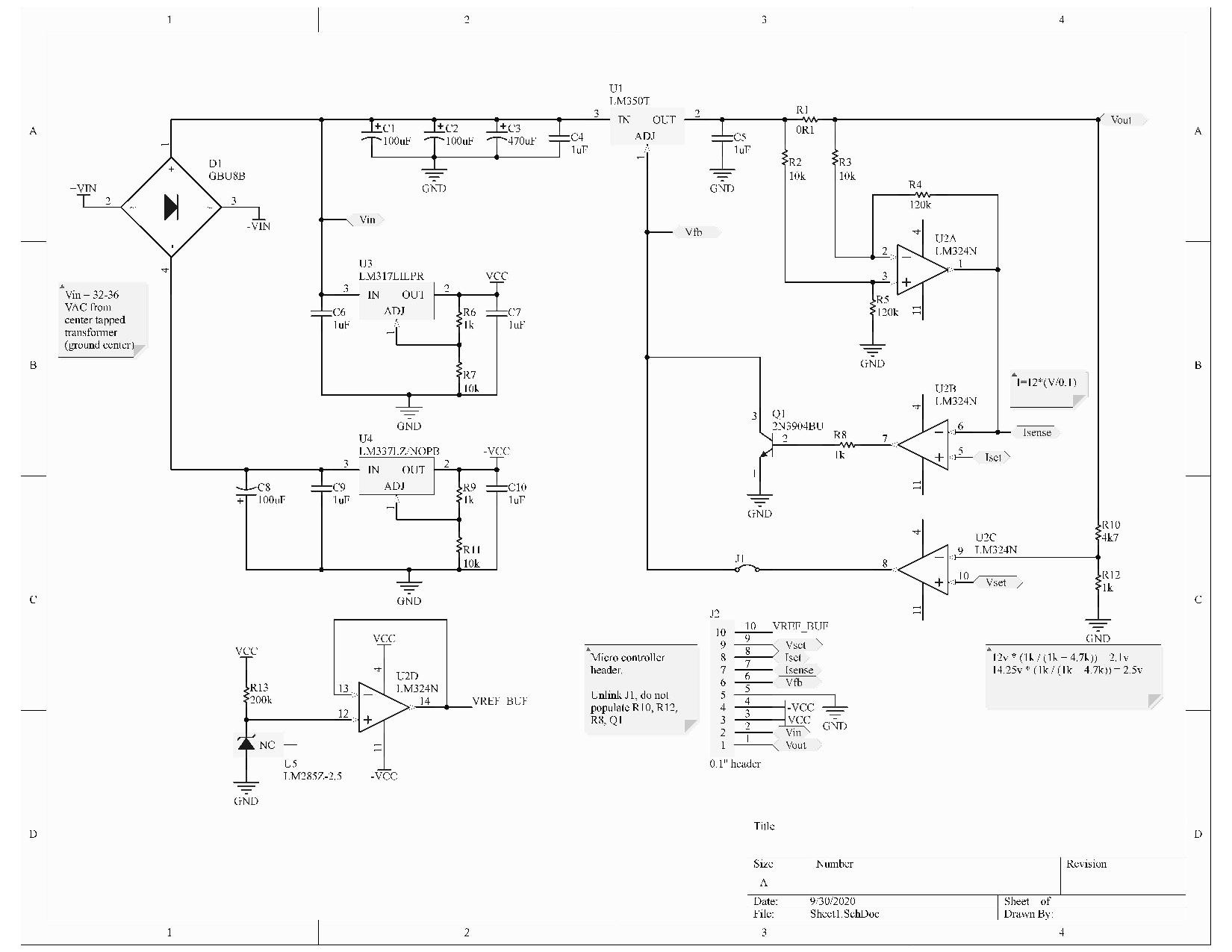
I've completed work on the schematic for the PCB.
Firstly, I added provisions for the supply to be controlled by a microcontroller. This can be done by depopulating some parts, cutting a jumper, and connecting it to the header. I've added all the necessary connections for good functionality.
Secondly, I have buffered the voltage reference. Although it wasn't under much load, it was becoming a problem. I had a spare opamp in the LM324 so it is not big deal.
Additionally, I've massively increased the input capacitance. I was having many problems with this and it took a while to nail down. About 600 uF seems to do the trick. Lastly, I changed around some component values to be more standard and more functional. The output voltage divider was giving me trouble, and I was only able to get 11.7V. I've designed it with some headroom to reach a maximum of 14.25v. I'm pretty proud of that part, I was able to get it down to 5 unique resistor values!
I have a list of features I'd want to add, but haven't for the time being. My big goal was to allow it to be supplied from a single +16v supply. As the negative rail has very little current draw, I was going to use a switched capacitance converter to create the -12v volts or so, but the only converters I can find have a maximum input voltage of +12v, when my +VCC rail is around 14. I also wanted to add some capacitors in the feedback loop or possibly a capacitance multiplier to the output. I have no way of doing transient or noise testing at the moment, so I'm going to hold off (I'm looking out for cheap scopes though).
Discussions
Become a Hackaday.io Member
Create an account to leave a comment. Already have an account? Log In.