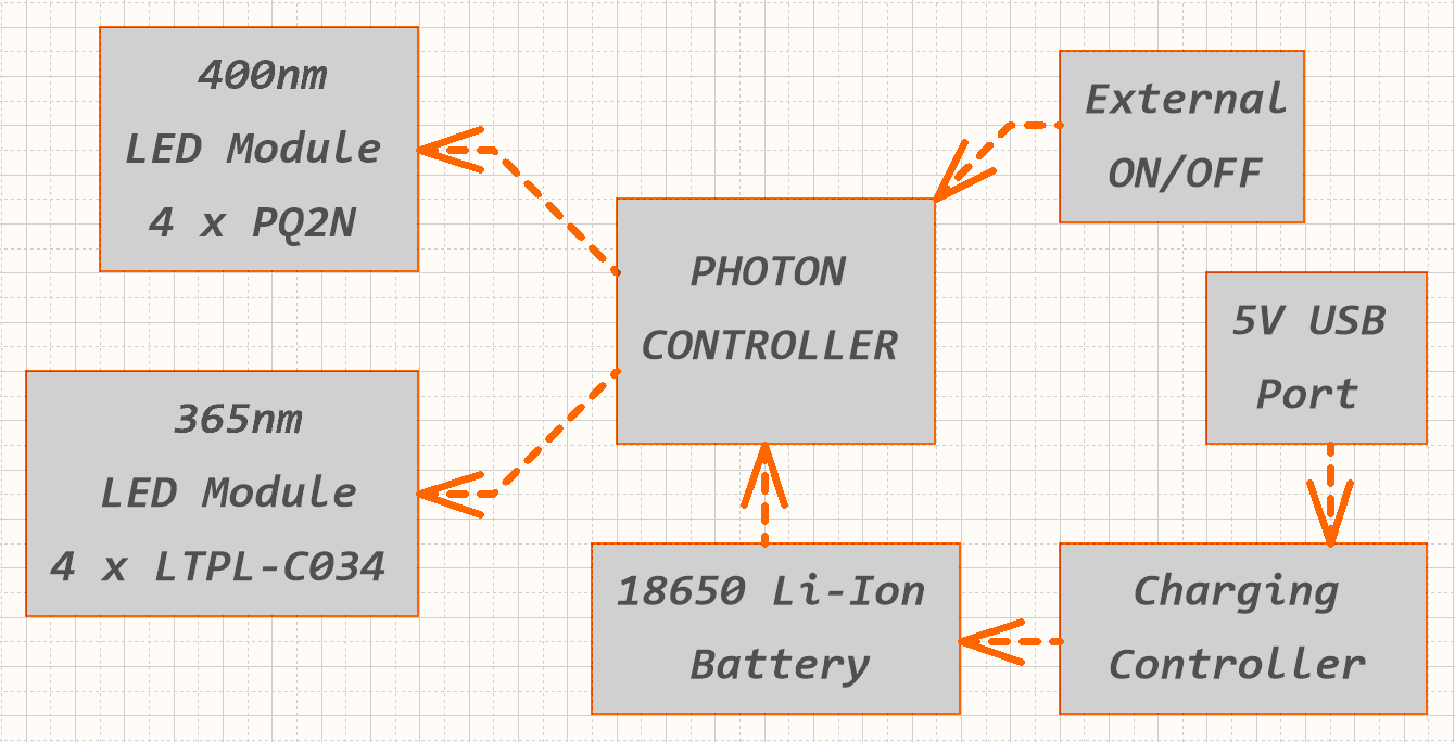
After the initial concept, a fully functional prototype has been made. Some functionality that has been added:
- LED Driver circuit that supports performance 365nm and economy 400nm LED module.
- Automatic recognition between different LED modules.
- Temperature protection of LED modules.
- Automatic power adjustment of LED modules that depends on their temperature.
- USB Rechargeable and user replaceable 18650 Li-Ion battery.
- Different modes of operation(continuous and momentary illumination).
- Externally triggered for use with an external controller.
- Aluminium substrate PCBs for better thermals.
All above mentioned improvements are documented in project schematics. Schematics include LED module PCB, Controller PCB and Connector PCB. Schematics are also available in higher resolution(.pdf) in the project repository. Special care was taken to reduce the number of unique components to make the assembly process more economical.
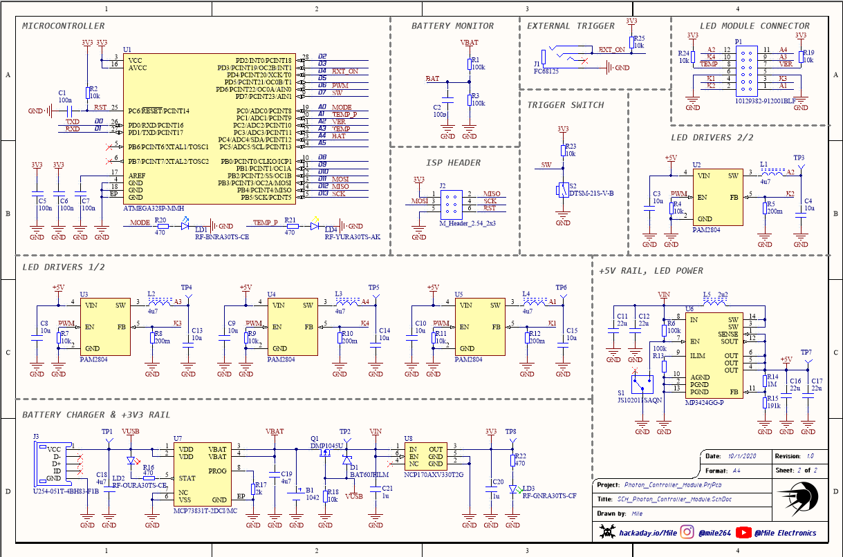
To make the assembly process easier and faster assembly drawings were generated. They are also available in .pdf format.

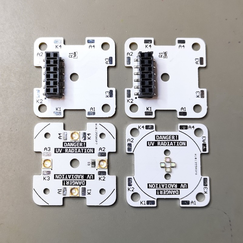
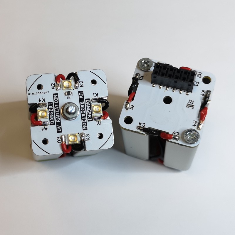
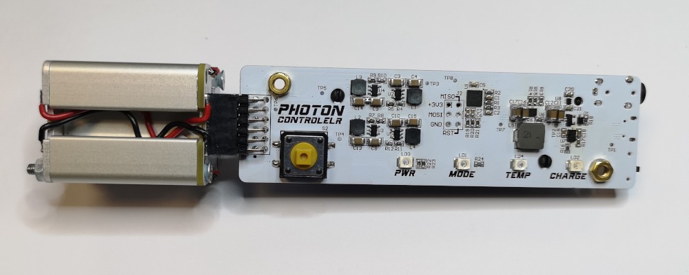
And finally here are some pictures of assembled modules. White colour of the solder mask was chosen because it is more reflective than the default green. This will help in reflecting UV radiation of LEDs outward.
 |  |
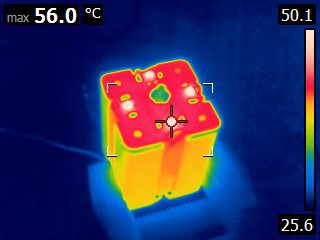
After assembling LED modules I did some testing. Since I am now using aluminum substrate PCBs I should have much better thermals. As it can be seen on the picture from thermal camera, temperatures are around 5°C lower, but what is more important is that there much better heat transfer to aluminum heatsink. This picture was taken after 30 minutes of operation so there is some "thermal lag" for heatsink to reach set temperature. This allows driving of LEDs at even higher power levels to achieve higher output power in shorter time periods.
 Mile
Mile
Discussions
Become a Hackaday.io Member
Create an account to leave a comment. Already have an account? Log In.