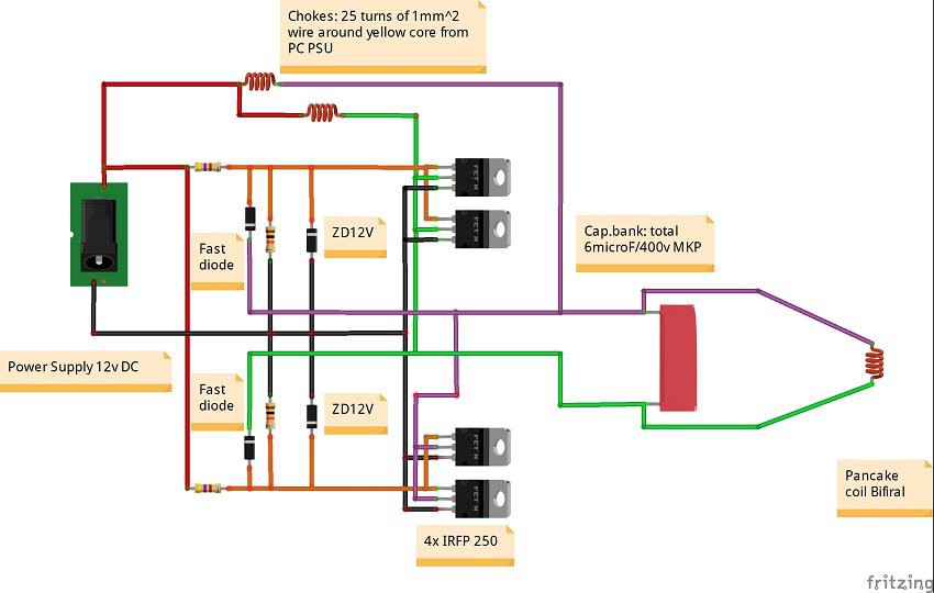
The simplest and cheapest way to build such a heater is with the help of an electric circuit called Mazzilli ZVS driver which is a modified version of the Royer Oscillator.
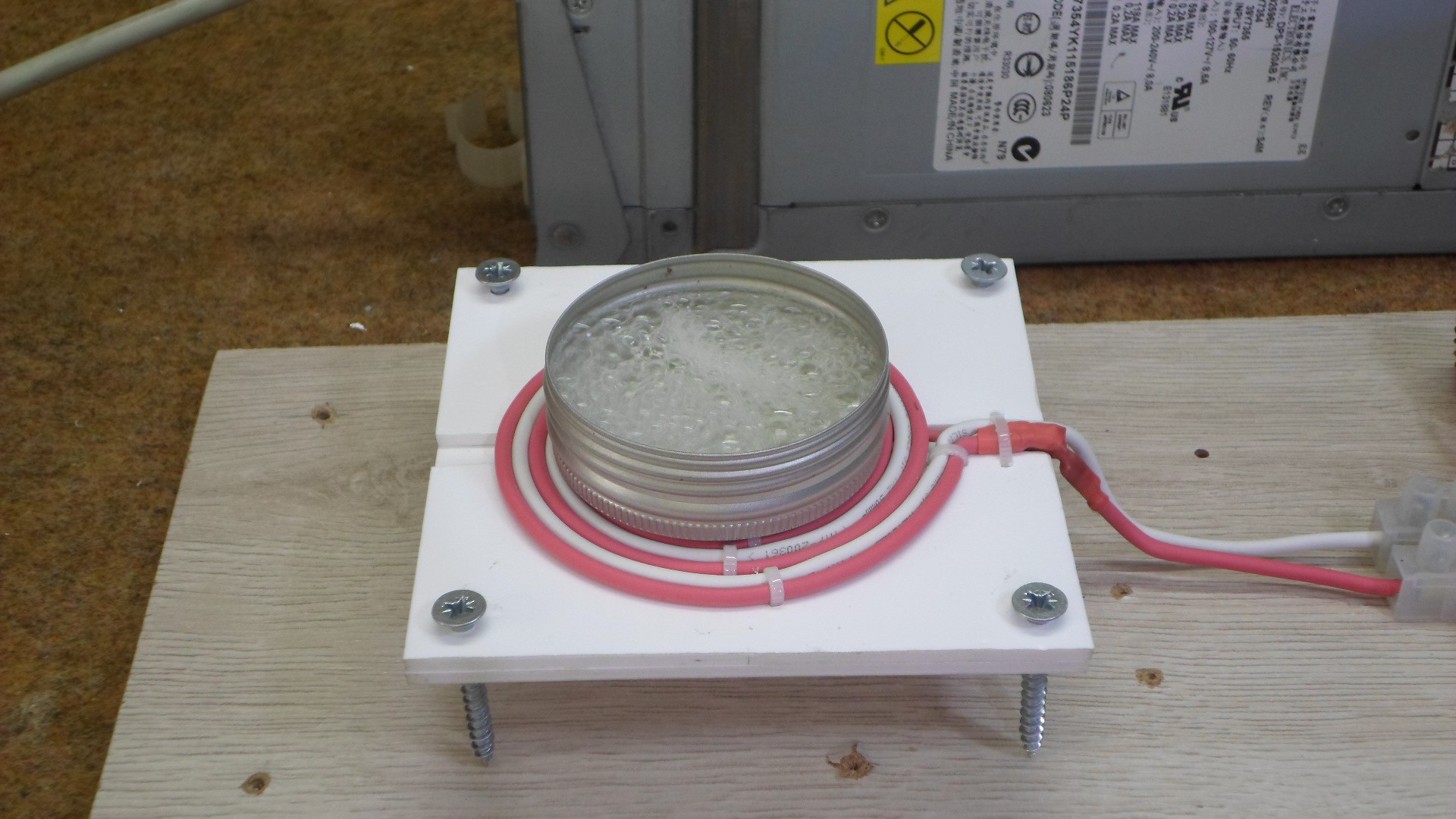
Unlike my previous induction heater, this one uses a bifilar wound flat coil patented by Nikola Tesla on 9 January 1894. The magnetic field created by one winding is therefore equal and opposite to that created by the other, resulting in a net magnetic field of zero (this neutralize any negative effects in the coil). In electrical terms, this means that the self-inductance of the coil is zero.
This Project was sponsored by NextPCB. You can help support me by checking them out at one of these links:
Register to get $5 coupon:
https://www.nextpcb.com?code=Mirko
Reliable Multilayer Boards Manufacturer:
https://www.nextpcb.com?code=Mirko
4 Layer PCB Boards 10pcs only $12:
https://www.nextpcb.com/pcb-quote?act=1
10% off - PCB & SMT Orders:
20%OFF - PCB & 15 % SMT Orders: https://www.nextpcb.com/activity/supp...
The simplest and cheapest way to build such a heater is with the help of an electric circuit called Mazzilli ZVS driver which is a modified version of the Royer Oscillator.
Unlike my previous induction heater, this one uses a bifilar wound flat coil patented by Nikola Tesla on 9 January 1894. The magnetic field created by one winding is therefore equal and opposite to that created by the other, resulting in a net magnetic field of zero (this neutralize any negative effects in the coil). In electrical terms, this means that the self-inductance of the coil is zero.

The device consist Two or four Power mosfet transistors mounted on large heatsinks with Fans for cooling. In my case mosfets are SW3205 . Also a very important part is the capacitive bank composed of several capacitors connected in parallel. In this particular case they are six quality MKP capacitors with a capacity of 1 micro farad each and a voltage of 400V. The two toroidal coils serve to limit the current. The working spool is a Bifilarly wound Flat (Pancake) coil.
IN FACT, THE PURPOSE OF THIS PROJECT WAS TO COMPARE THE EFFICIENCY OF SUCH A BIFILAR COIL WITH A STANDARD COIL.
The end result was that there was no significant difference between the two coils in this type of induction heater. Let me just mention that the bifirly coil is much harder to make. It is interesting that the heating coil is not heated after this and we can freely put our hand on it. This is due to the fact that the coil uses copper wire with silicone insulation that is temperature resistant and also very poor conductor of heat.

The device is powered by 12V Power Supply from old Server Computer.The power supply must provide a minimum 10 Ampers of current.
 mircemk