Measuring the temperature of a given environment is very important, because, through this parameter, it is possible to control various processes such as industrial ones, those related to incubators, processes for refrigerating small devices or large systems, and also in Central Processing Units (CPU) of computers, among other applications.
In addition to these applications, the appropriately configured temperature sensor can be used to activate other devices, when the ambient temperature is above or below a predetermined value, for example, the air conditioners act more intensely when the temperature of an environment is above the set value, causing more heat to be removed from the environment until it reaches the set temperature.
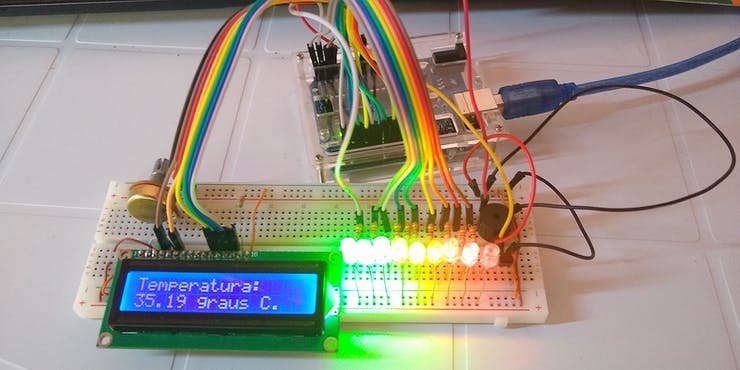
Thus, a similar application was developed in the case of the Didactic Thermometer using the LM35 temperature sensor, as shown in Figure 1.
Figure 1 - Didactic Thermometer Case Using the LM35 Sensor.
With the development of this Didactic Thermometer case, you will learn both how to assemble the basic circuit using the Arduino as in previous projects, and how to program it.
The Didactic Thermometer implemented has a simple structure, with the LCD display (Liquid Crystal Display), the LM35 temperature sensor, 3 green Led's, 3 yellow Led's, 3 red LEDs and a Buzzer.
The LM35 temperature sensor detects the ambient temperature, and transmits the value to the Arduino, which is responsible for processing the signal, and then activating the corresponding LEDs in the Buzzer according to the temperature range configured in the program.
In this article, you will learn how to program and use the LM35 temperature sensor, as this is an analog temperature sensor with an important precision margin.
Therefore, through this article you will learn:
- Know the structure of the case of the Didactic Thermometer and the Analogic Temperature Sensor LM35;
- Understand how the LM35 Analog Temperature Sensor works well with other devices in the house;
- Perform the Communication between the LM35 Analog Temperature Sensor, the Led's, the Buzzer, the LCD display, and the Arduino UNO
- Couple the structure of the LM35 Analog Temperature Sensor and the other components to the didactic case developed.
- Develop a JLCPCB Printed Circuit Board for this project
Now, we will start the complete presentation of the development of the Didactic Thermometer Using the LM35 Temperature Sensor.
Developing the Thermometer Project
This project consists of presenting a didactic model of a thermometer using the LM35 temperature sensor with the UNO Arduino development board.
The project basically consists of the temperature sensor, responsible for detecting the ambient temperature, and through its housing, converting that temperature into an analog signal.
Led's and the Buzzer will be used as beacons and, finally, we have the LCD display that will show the process temperature value, as shown in Figure 2.

Figure 2 - Circuit proposed for the operation of the Didactic Thermometer.
The LM35 temperature sensor consists of a housing with a shape close to that of a semi-cylinder with three pins.
According to its datasheet, the sensor has a resolution of 10mV / ºC, that is, every 1 degree Celsius, it supplies 10 mV in its output. Equation 1 illustrates the conversion.

Equation 1 - Temperature Conversion on the LM35 Sensor. Source: Texas Instruments.
In this way, the Arduino captures the signal, so that it can be converted in a range from 0 to 1023 (analog value) into a signal from 0V to 5V (voltage signal).
After that, a linear interpolation is made between these values and it is possible to find the voltage value corresponding to the temperature captured by the sensor.
Finally, this value is divided by the resolution and thus the temperature value registered by the sensor is found. Figure 4 illustrates the LM35 temperature sensor.
All communication of the Didactic Thermometer will be done through the LCD display, which will send messages to the user.
The LM35 sensor will convert the temperature of the place where it is, through its wrapping, into an analog value. Soon after, this value will be sent by its central pin to an analog pin from Arduino UNO.
Then, through the developed program, the analog value will be converted into a voltage value between 0 and 5 volts. According to the temperature value obtained, the Buzzer signal will be activated for a short period of time, and immediately afterward a number of Led's will be lit for the visual indication of the temperature range. Finally, the temperature value registered by the sensor is shown on the LCD display.
To set up the experiment, first, make sure that your Arduino is turned off by disconnecting it from the USB cable. Now, take the components and connect everything as shown in Figure 6 below.
Figure 3 - Wiring diagram for the proposed circuit.
The Led's circuit consists of 9 LEDs, 3 green, 3 yellow and 3 red, with their respective 220 Ω resistors. Each Led represents a variation of 5 degrees celsius, starting with the first green Led and ending with the last red Led.
Most LEDs were connected to digital pins so that the intensity of the pins would be maximum, however, 3 analog pins were used per quantity of LEDs, and for these, the value of 1023 representing the high logic level of the LEDs was used. digital pins.
As the LEDs are connected with the anode at 5Volts, all are activated with a low logic level on the connected pins.
The LCD display circuit will be the standard using the 4-bit connection (D4, D5, D6, and D7), together with the 10 kΩ potentiometers responsible for the contrast, and a 220 resist resistor connected to the anode pin.
The Arduino Uno will be responsible for processing the signal of the circuit as a whole and supply the power and reference for the protoboard bus, and thus supply the circuits of the developed project.
From the scheme presented above, we will understand the operation of the programming logic developed.
Development of System Programming Logic
All the programming logic of the Didactic Thermometer was developed as commented on the following program:
#include <LiquidCrystal.h>//importando a biblioteca das funçoes do LCD
//pinos de interface da biblioteca
LiquidCrystal lcd(12, 11, 5, 4, 3, 2);
int lm35 = A0;//pino do sensor lm35 conectado ao pino analogico A0 inicializado com o valor 0.
float valor_lm35 = 0;//valor que será lido pelo pino analogico do sensor lm35 inicializado com o valor 0.
float temperatura = 0;//varaivel utilizada para receber e armazenar o valor de tempersrura convertido do valor analogico.
//INICIO - intervalos de temperatura em graus celsius
int temp0=0;
int temp1=5;
int temp2=10;
int temp3=15;
int temp4=20;
int temp5=25;
int temp6=30;
int temp7=35;
int temp8=40;
int temp9=45;
//FIM - intervalos de temperatura em graus celsius
// INICIO - verificadores do buzzer
int aux01;
int aux12;
int aux23;
int aux34;
int aux45;
int aux56;
int aux67;
int aux78;
int aux89;
/*
* Os veriicadores aux forma utilizados para verificar se o buzzer ja foi acionada a cada rodada da função loop. Assim que o
* intervalo de temepratura é selecionado, ´pe verificado se o aculumador aux possui um valor igual a zero. Caso seja igual a zero,
* o buzzer é acionado e o contador é incrementado, e ocm isso, ele se rona diferente de zero, e na oroxima rodada da função
* loop o buzzer nao será acionado. E Caso o intervalo de temperatira mude, o contador será zerado no proxima intervbalo que entrar,
* e o sistema será adotado pelo proximo contador.
*/
//FIM - verificadores do buzzer
//INICIO - leds indicativos
int Led_verde1 = A4;//0
int Led_verde2 = A5;//1
int Led_verde3 = 6;//6
int Led_laranja1 = 7;//7
int Led_laranja2 = 8;//8
int Led_laranja3 = 9;//9
int Led_vermelho1 = 10;//10
int Led_vermelho2 = 13;//13
int Led_vermelho3 = A3;//porta analogica A1
//FIM - leds indicativos
//INICIO - pino do buzzer
int pino_buzzer = A2;// pino correspondente ao buzzer
//FIM - pino do buzzer

void setup() {
//inicio - definindo os pinos do leds como saida
pinMode(Led_verde1,OUTPUT);
pinMode(Led_verde2,OUTPUT);
pinMode(Led_verde3,OUTPUT);
pinMode(Led_laranja1,OUTPUT);
pinMode(Led_laranja2,OUTPUT);
pinMode(Led_laranja3,OUTPUT);
pinMode(Led_vermelho1,OUTPUT);
pinMode(Led_vermelho2,OUTPUT);
pinMode(Led_vermelho3,OUTPUT);
//fim - definindo os pinos do leds como saida

pinMode(pino_buzzer,OUTPUT);//definindo o pino do buzzer como saida
pinMode(lm35,INPUT);

//  Numero de linhas e colunas do LCD utilizado
lcd.begin(16, 2);

// Funcao responsavel por retornar a mensagem no LCD
lcd.setCursor(2,0);//setando o cursor do LCD na coluna 2 linha 0
lcd.print("SILICIOS LAB");//mensagem enviada para o LCD
lcd.setCursor(0,1);//setando o cursor do LCD na coluna 2 linha 1
lcd.print("TERMOM. DIDATICO");//mensagem enviada para o LCD
delay(4000);//aguarda 4 segundos para iniciar
lcd.clear();//apaga os caracteres no LCD
}

void loop() {

lcd.setCursor(0,0);//desloca o cursor para a posição especifica do texto da contagem
lcd.clear();//limpa a contagem anterior
valor_lm35=analogRead(lm35);//ler o valor analogico enviado pelo pino analogico utilizado
temperatura=(((5*valor_lm35)/1023)/0.01);
/*
*

*******INICIO - CACULO DE CONVERSAO DO LM34**********
temperatura_t=temperatura_v/10mV = temperatura_v/0.01;
5v (valor de tensao maxima no pino) -----> 1023 (valor analogico do pino)
xv (valor de tensao maxima no pino) -----> y (valor analogico do pino)
x = [(5*y)/1023]V
resolução do lm34 = 10mV//ºC = 0.01V/ºC
temperatura = x / resolução =  [(5*y)/1023]V / [0.01]V/ºC = {(5*y)/1023] / [0.01]}ºC
********FIM - CACULO DE CONVERSAO DO LM34*************
*
*/

//INICIO -  CONDIÇOES DOS LEDS
if(temp0<temperatura&&temperatura<temp1){
aux12=0;//zerando os contadores dos outros intervalos
aux23=0;
aux34=0;
aux45=0;
aux56=0;
aux67=0;
aux78=0;
aux89=0;

//
if(aux01==0)//verificando se o buzzer ja foi acionado nessa rodada da função loop
{
analogWrite(pino_buzzer,1023);//ativa o pino analogico do buzzer para que ele sinalize a mudança de temperatura
delay(30);//deixa o buzzer ativado por 1 segundo
analogWrite(pino_buzzer,0);//desativa o pino do buzzer
}

else{

}
aux01++;//incrementado o acumulador para que o buzzer nao seja acionado mais de uma vez durante o mesmo intervalo de temperatura.
analogWrite(Led_verde1, 0);//Leds indicativos
analogWrite(Led_verde2,1023);
digitalWrite(Led_verde3,HIGH);
digitalWrite(Led_laranja1,HIGH);
digitalWrite(Led_laranja2, HIGH);
digitalWrite(Led_laranja3, HIGH);
digitalWrite(Led_vermelho1,HIGH);
digitalWrite(Led_vermelho2,HIGH);

analogWrite(Led_vermelho3,1023);

lcd.clear();//apaga os caracteres no LCD
lcd.setCursor(0, 0);// inicia o curso do LCD na coluna 0, linha 0
lcd.print("Temperatura:");//mensagem enviada para o LCD
lcd.setCursor(0, 1);// inicia o curso do LCD na coluna 0, linha 0

// lcd.print(aux);//mostra o valor da variavel "moedas" no LCD

lcd.setCursor(6,1);
lcd.print("graus C.");//mensagem enviada para o LCD
delay(100);
lcd.clear();
}

else
if(temp1<temperatura&&temperatura<temp2)
{
aux01=0;
aux23=0;
aux34=0;
aux45=0;
aux56=0;
aux67=0;
aux78=0;
aux89=0;

if(aux12==0)
{
analogWrite(pino_buzzer,1023);//ativa o pino analogico do buzzer para que ele sinalize a mudança de temperatura
delay(30);//deixa o buzzer ativado por 1 segundo
analogWrite(pino_buzzer,0);//desativa o pino do buzzer
}

else{}

aux12++;
analogWrite(Led_verde1, 0);
analogWrite(Led_verde2, 0);
digitalWrite(Led_verde3,HIGH);
digitalWrite(Led_laranja1,HIGH);
digitalWrite(Led_laranja2, HIGH);
digitalWrite(Led_laranja3, HIGH);
digitalWrite(Led_vermelho1,HIGH);
digitalWrite(Led_vermelho2,HIGH);
analogWrite(Led_vermelho3,1023);

lcd.clear();
lcd.setCursor(0, 0);// inicia o curso do LCD na coluna 0, linha 0
lcd.print("Temperatura:");//mensagem enviada para o LCD
lcd.setCursor(0, 1);// inicia o curso do LCD na coluna 0, linha 0
lcd.setCursor(6,1);
lcd.print("graus C.");//mensagem enviada para o LCD
delay(100);
lcd.clear();
}

else
if(temp2<temperatura&&temperatura<temp3)
{
aux01=0;
aux12=0;
aux34=0;
aux45=0;
aux56=0;
aux67=0;
aux78=0;
aux89=0;

if(aux23==0)
{
analogWrite(pino_buzzer,1023);//ativa o pino analogico do buzzer para que ele sinalize a mudança de temperatura
delay(30);//deixa o buzzer ativado por 1 segundo
analogWrite(pino_buzzer,0);//desativa o pino do buzzer
}
else
{}

aux23++;
analogWrite(Led_verde1, 0);
analogWrite(Led_verde2, 0);
digitalWrite(Led_verde3,LOW);
digitalWrite(Led_laranja1,HIGH);
digitalWrite(Led_laranja2, HIGH);
digitalWrite(Led_laranja3, HIGH);
digitalWrite(Led_vermelho1,HIGH);
digitalWrite(Led_vermelho2,HIGH);
analogWrite(Led_vermelho3,1023);

lcd.clear();
lcd.setCursor(0, 0);// inicia o curso do LCD na coluna 0, linha 0
lcd.print("Temperatura:");//mensagem enviada para o LCD
lcd.setCursor(0, 1);// inicia o curso do LCD na coluna 0, linha 0
lcd.setCursor(6,1);
lcd.print("graus C.");//mensagem enviada para o LCD
delay(100);
lcd.clear();
}
else
if(temp3<temperatura&&temperatura<temp4)
{
aux01=0;
aux12=0;
aux23=0;
aux45=0;
aux56=0;
aux67=0;
aux78=0;
aux89=0;

if(aux34==0)
{
analogWrite(pino_buzzer,1023);//ativa o pino analogico do buzzer para que ele sinalize a mudança de temperatura
delay(30);//deixa o buzzer ativado por 1 segundo
analogWrite(pino_buzzer,0);//desativa o pino do buzzer
}

else{}

aux34++;
analogWrite(Led_verde1, 0);
analogWrite(Led_verde2, 0);
digitalWrite(Led_verde3,LOW);
digitalWrite(Led_laranja1,LOW);
digitalWrite(Led_laranja2, HIGH);
digitalWrite(Led_laranja3, HIGH);
digitalWrite(Led_vermelho1,HIGH);
digitalWrite(Led_vermelho2,HIGH);
analogWrite(Led_vermelho3,1023);

lcd.clear();
lcd.setCursor(0, 0);// inicia o curso do LCD na coluna 0, linha 0
lcd.print("Temperatura:");//mensagem enviada para o LCD
lcd.setCursor(0, 1);// inicia o curso do LCD na coluna 0, linha 0
lcd.setCursor(6,1);
lcd.print("graus C.");//mensagem enviada para o LCD
delay(100);
lcd.clear();
}

else
if(temp4<temperatura&&temperatura<temp5)
{
aux01=0;
aux12=0;
aux23=0;
aux34=0;
aux56=0;
aux67=0;
aux78=0;
aux89=0;

if(aux45==0)
{
analogWrite(pino_buzzer,1023);//ativa o pino analogico do buzzer para que ele sinalize a mudança de temperatura
delay(30);//deixa o buzzer ativado por 1 segundo
analogWrite(pino_buzzer,0);//desativa o pino do buzzer
}

else{}

aux45++;
analogWrite(Led_verde1, 0);
analogWrite(Led_verde2, 0);
digitalWrite(Led_verde3,LOW);
digitalWrite(Led_laranja1,LOW);
digitalWrite(Led_laranja2, LOW);
digitalWrite(Led_laranja3, HIGH);
digitalWrite(Led_vermelho1,HIGH);
digitalWrite(Led_vermelho2,HIGH);
analogWrite(Led_vermelho3,1023);

lcd.clear();
lcd.setCursor(0, 0);// inicia o curso do LCD na coluna 0, linha 0
lcd.print("Temperatura:");//mensagem enviada para o LCD
lcd.setCursor(0, 1);// inicia o curso do LCD na coluna 0, linha 0
lcd.setCursor(6,1);
lcd.print("graus C.");//mensagem enviada para o LCD
delay(100);
lcd.clear();

}

else
if(temp5<temperatura&&temperatura<temp6)
{
aux01=0;
aux12=0;
aux23=0;
aux34=0;
aux45=0;
aux67=0;
aux78=0;
aux89=0;

if(aux56==0)
{
analogWrite(pino_buzzer,1023);//ativa o pino analogico do buzzer para que ele sinalize a mudança de temperatura
delay(30);//deixa o buzzer ativado por 1 segundo
analogWrite(pino_buzzer,0);//desativa o pino do buzzer
}

else

{
}

aux56++;
analogWrite(Led_verde1, 0);
analogWrite(Led_verde2, 0);
digitalWrite(Led_verde3,LOW);
digitalWrite(Led_laranja1,LOW);
digitalWrite(Led_laranja2, LOW);
digitalWrite(Led_laranja3, LOW);
digitalWrite(Led_vermelho1,HIGH);
digitalWrite(Led_vermelho2,HIGH);
analogWrite(Led_vermelho3,1023);

float aux=temperatura;//variavel utilizada para armazenar a leitura autal do sensor

lcd.clear();
lcd.setCursor(0, 0);// inicia o curso do LCD na coluna 0, linha 0
lcd.print("Temperatura:");//mensagem enviada para o LCD
lcd.setCursor(0, 1);// inicia o curso do LCD na coluna 0, linha 0
lcd.print(temperatura);//mostra o valor da variavel "moedas" no LCD
lcd.setCursor(6,1);
lcd.print("graus C.");//mensagem enviada para o LCD
delay(100);
lcd.clear();
}
else
if(temp6<temperatura&&temperatura<temp7)
{
aux01=0;
aux12=0;
aux23=0;
aux34=0;
aux45=0;
aux56=0;
aux78=0;
aux89=0;

if(aux67==0){
analogWrite(pino_buzzer,1023);//ativa o pino analogico do buzzer para que ele sinalize a mudança de temperatura
delay(30);//deixa o buzzer ativado por 1 segundo
analogWrite(pino_buzzer,0);//desativa o pino do buzzer
}

else{}

aux67++;
analogWrite(Led_verde1, 0);
analogWrite(Led_verde2, 0);
digitalWrite(Led_verde3,LOW);
digitalWrite(Led_laranja1,LOW);
digitalWrite(Led_laranja2, LOW);
digitalWrite(Led_laranja3, LOW);
digitalWrite(Led_vermelho1,LOW);
digitalWrite(Led_vermelho2,HIGH);
analogWrite(Led_vermelho3,1023);

lcd.clear();
lcd.setCursor(0, 0);// inicia o curso do LCD na coluna 0, linha 0
lcd.print("Temperatura:");//mensagem enviada para o LCD
lcd.setCursor(0, 1);// inicia o curso do LCD na coluna 0, linha 0
lcd.print(temperatura);//mostra o valor da variavel "moedas" no LCD
lcd.setCursor(6,1);
lcd.print("graus C.");//mensagem enviada para o LCD
delay(100);
lcd.clear();
}
else
if(temp7<temperatura&&temperatura<temp8)
{
aux01=0;
aux12=0;
aux23=0;
aux34=0;
aux45=0;
aux56=0;
aux67=0;
aux89=0;

if(aux78==0){
analogWrite(pino_buzzer,1023);//ativa o pino analogico do buzzer para que ele sinalize a mudança de temperatura
delay(30);//deixa o buzzer ativado por 1 segundo
analogWrite(pino_buzzer,0);//desativa o pino do buzzer
}

else{}

aux78++;
analogWrite(Led_verde1, 0);
analogWrite(Led_verde2, 0);
digitalWrite(Led_verde3,LOW);
digitalWrite(Led_laranja1,LOW);
digitalWrite(Led_laranja2, LOW);
digitalWrite(Led_laranja3, LOW);
digitalWrite(Led_vermelho1,LOW);
digitalWrite(Led_vermelho2,LOW);
analogWrite(Led_vermelho3,1023);
lcd.clear();
lcd.setCursor(0, 0);// inicia o curso do LCD na coluna 0, linha 0
lcd.print("Temperatura:");//mensagem enviada para o LCD
lcd.setCursor(0, 1);// inicia o curso do LCD na coluna 0, linha 0
lcd.print(temperatura);//mostra o valor da variavel "moedas" no LCD
lcd.setCursor(6,1);
lcd.print("graus C.");//mensagem enviada para o LCD
delay(100);
lcd.clear();
}
else if(temp8<temperatura&&temperatura<temp9){
aux01=0;
aux12=0;
aux23=0;
aux34=0;
aux45=0;
aux56=0;
aux67=0;
aux78=0;
if(aux89==0){
analogWrite(pino_buzzer,1023);//ativa o pino analogico do buzzer para que ele sinalize a mudança de temperatura
delay(30);//deixa o buzzer ativado por 1 segundo
analogWrite(pino_buzzer,0);//desativa o pino do buzzer
}
else{}
aux89++;
analogWrite(Led_verde1, 0);
analogWrite(Led_verde2, 0);
digitalWrite(Led_verde3,LOW);
digitalWrite(Led_laranja1,LOW);
digitalWrite(Led_laranja2, LOW);
digitalWrite(Led_laranja3, LOW);
digitalWrite(Led_vermelho1,LOW);
digitalWrite(Led_vermelho2,LOW);
analogWrite(Led_vermelho3,0);
lcd.clear();
lcd.setCursor(0, 0);// inicia o curso do LCD na coluna 0, linha 0
lcd.print("Temperatura:");//mensagem enviada para o LCD
lcd.setCursor(0, 1);// inicia o curso do LCD na coluna 0, linha 0
lcd.print(temperatura);//mostra o valor da variavel "moedas" no LCD
lcd.setCursor(6,1);
lcd.print("graus C.");//mensagem enviada para o LCD
delay(100);
lcd.clear();
}
else  {
// inicia o curso do LCD na coluna 0, linha 1
lcd.setCursor(0, 0);// inicia o curso do LCD na coluna 0, linha 0
// print the number of seconds since reset:
lcd.print("Temp. fora de ");//mensagem enviada para o LCD
lcd.setCursor(0, 1);
lcd.print("escala");//mensagem enviada para o LCD
lcd.clear();//apaga os caracteres no LCD
delay(100);
}
//FIM -  CONDIÇOES DOS LEDS
}
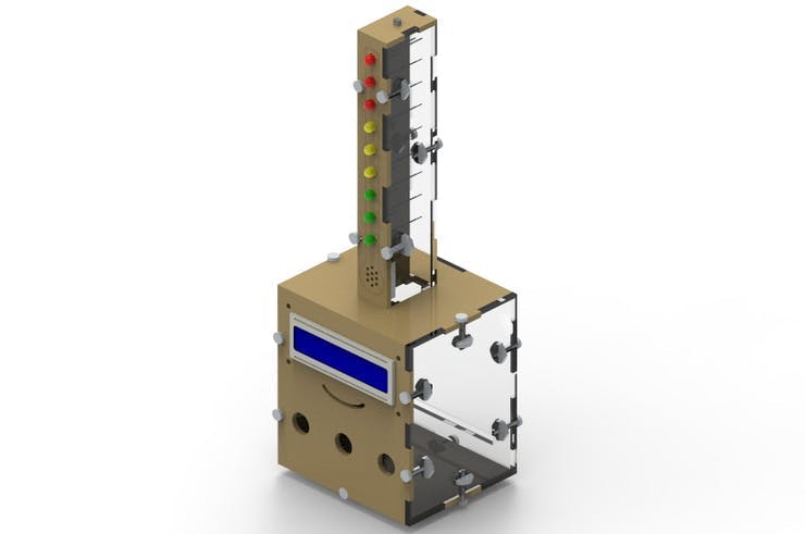
For this project, a proprietary case was developed, which will receive the LM35 temperature sensor, the LCD display, the Buzzer signal, the LEDs, leaving only the resistors and pins of the Arduino UNO remaining, so that it can be used in a didactic way, as shown in Figure 7.

Figure 4 - Mechanical Structure of the Termometer with Arduino.
Next, we will present the structure of the printed circuit board to control the project.
Developing the Printed Circuit Board
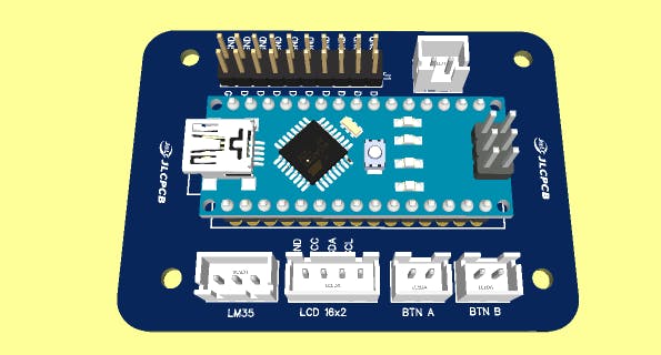
From the design of the thermometer with Arduino, a JLCPCB Printed Circuit Boardwas developed. The printed circuit board is shown in the figure below.

This board has an Arduino, 5 JST connectors, and a pin bar.
Three connectors are used to connect the structure buttons. In addition, we have JST connectors to connect the LCD Display and the LM35 temperature sensor.
Finally, we have a pin bar that allows us to connect the LED tower of the thermometer.
The printed circuit board circuit was developed from the electronic diagram below and you can download the files at the end of the article.

Figure 6 - Electronic Schematic of the Project.
After downloading the files, you can purchase 10 free units on the JLCPCB Factory website.
Through this electronic schematic, you can set up your project and develop several creative activities with the Arduino.
Conclusion
Therefore, from the development of this project, it was possible to know the structure of the LM35 temperature sensor, of the Buzzer flag.
In addition, we can analyze the communication with the Arduino Uno through the developed program.
As the temperature sensor has a conversion factor that depends on its housing, the measured temperature value showed an error of approximately 3 degrees when compared to the temperature in the region where the measurement was made.
However, the value used to compare was the temperature of the region, not the value of the location.
Acknowledgment
We appreciate the support of the JLCPCB PCB Factoryfor supporting the development of this project.
In addition, we would like to thank the Robô Lúdico Brazillian Schoolfor the development of the project.

