 Jeremy
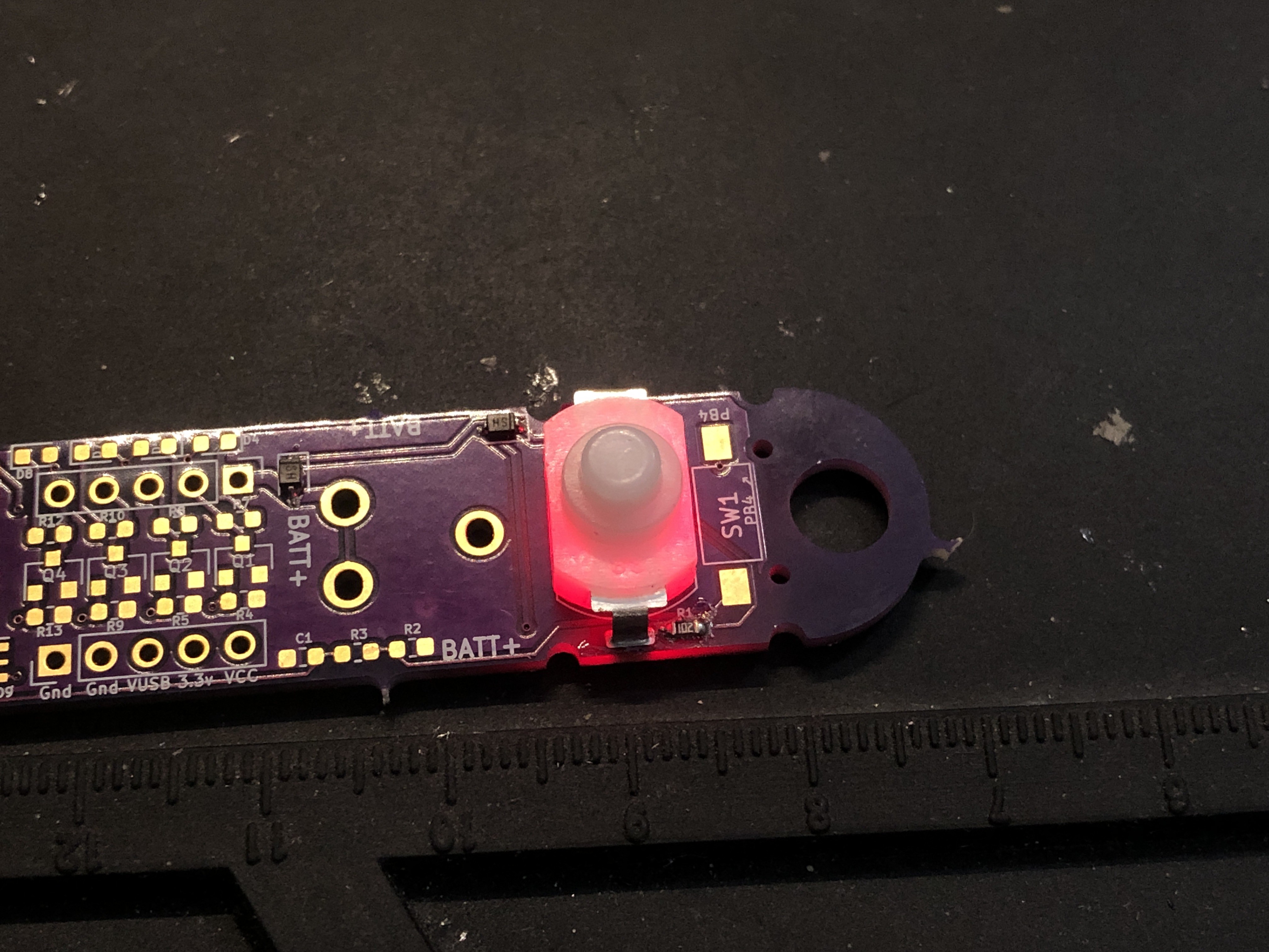
When I found the KAN-15 switches, I didn't think at all about their light properties. I was looking at the overall size, current ratings, and how the pins were setup.
It wasn't until I built the prototype board, which had the power LED just a little too close to the switch, that I noticed how well the switch picked up the LED light and diffused it wonderfully.
I got excited and realized I could embed LEDs under the switch.
Inside the PCB!

I don't know what I was thinking, but my first thought was to embed an LED inside the PCB under the switch. How hard could it be?
Not too hard actually, but also kind of a pain.

Bottom: the empty plated hole. Top: the LED soldered in place.
It turns out if you get clever with placing a couple of plated holes and edge cuts, Oshpark will send you a PCB with some decent plated slots. I followed the method for creating castellated edges.

The problem is that it's a bit tricky to get the LED in the slot and soldered. It's not particularly hard, but I wouldn't want to do this on a bit run of boards.
Either way, the results are pretty good.
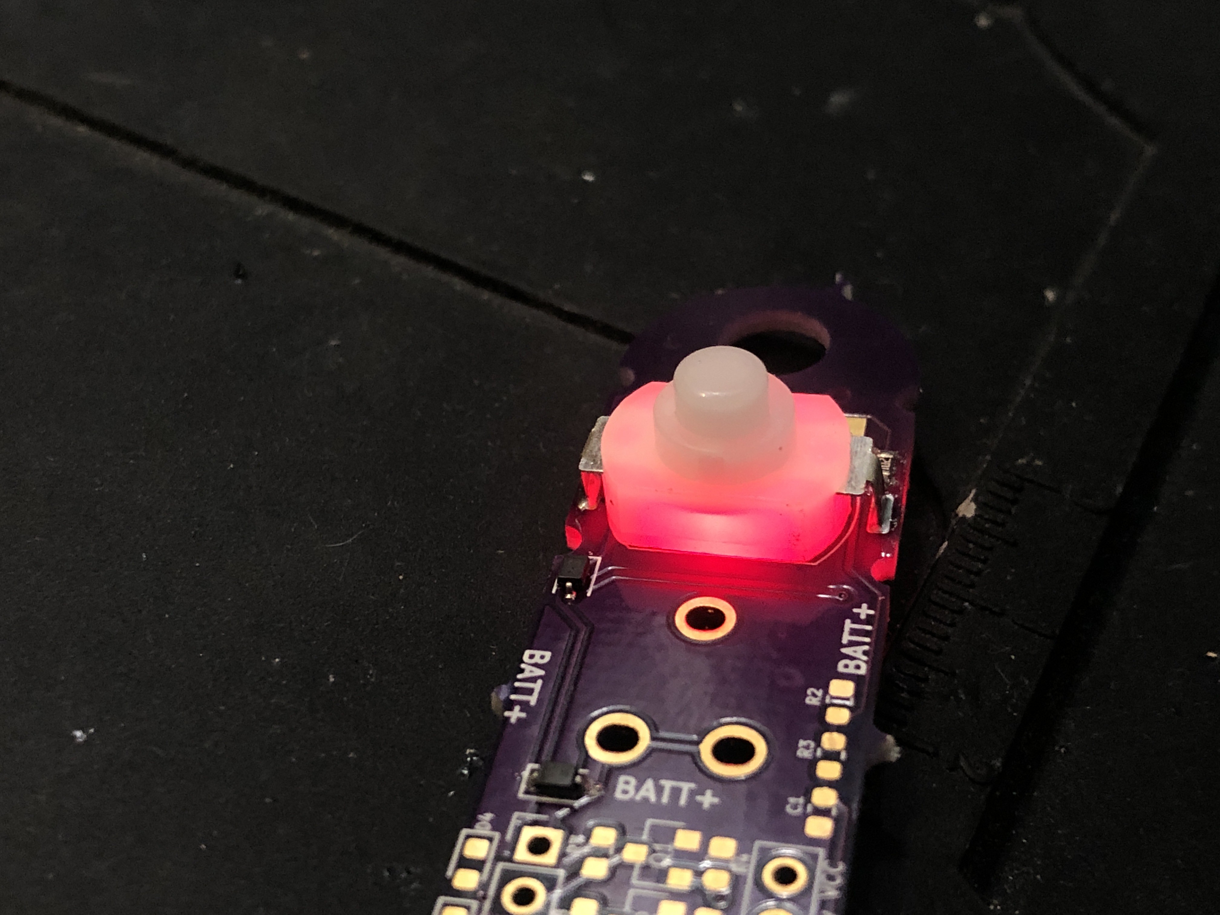
Good results, but not scalable.
What if I 3D printed a small shim to go between the PCB and the switch with a cavity for the LED? Stay tuned for the next log which will break that down.
Discussions
Become a Hackaday.io Member
Create an account to leave a comment. Already have an account? Log In.