Here is the PCB rendering in KiCAD

Here is the PCB
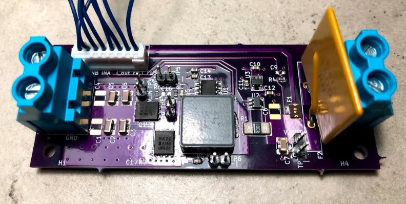
On the left are the screw terminals to apply the 12V. C1-C6 are the input capacitors. The transistors are SIRA20DP. They are controlled by a MP18021. Why the MP18021? It can handle -5V on the switching node. It also has the integrated diode for high side driver. The inductor is a 1uH SRP1265A. The output current is measured using a 0.001 Ohm sense resistor, with Kelvin connections to the INA180 current sensor. There is a small output capacitor. Then, to connect to the supercapacitor (and make sure I don't have ~200 Amps in the event of a short while probing), I used a 15A 0ZRN1500FF1A polymeric fuse. The terminals on the right are for the load. The 8-pin JST connector connects to the controller.
Discussions
Become a Hackaday.io Member
Create an account to leave a comment. Already have an account? Log In.