 Tim
TimUsing LEDs as light sensors is a hack tried by many. If operated under reverse bias conditions, LEDs act as photodiodes. Due to their small size, the generated photocurrent is extremely small, so some tricks have to be employed to measure it.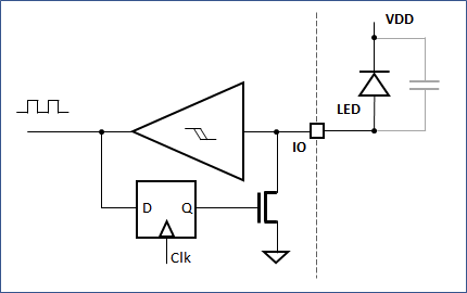
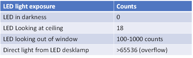
I tested the concept with a red 5mm LED. Counting time was 500 ms. With these settings it was clearly possible to discern different light level from total darkness to direct bright light as shown in the table above.
Since the GPIO can be reconfigured, it would be possible to use an LED in dual function as a light detector and indicator without having to add additional parts.
A quick estimation how much current we are measuring:
- Total charge in the charge LED is given by Q=C*V. Then we can calculate the Photocurrent by Iph=Q/tcnt, where tcnt = twindow/cnts, the time for a single count.
- => Iph = cnts*C*V/twindow
- The total discharge voltage is 5* (0.8-0.2) = 3V (Upper-lower trigger voltage)
- Let's assume 50pF for the LED junction capacitance + parasitic capactiance of the breadboard.
- Twindow= 500ms
=> Iph = cnts * 50pF*3V/500ms = cnts * 300 pA
One count corresponds to only 300 pA of photocurrent!
Of course, there are numerous imperfections in this set up, including leakage currents and nonlinear C(V) behavior, so we cannot expect a highly linear light sensor from this. But it should be sufficient if only a threshold needs to be detected.
Discussions
Become a Hackaday.io Member
Create an account to leave a comment. Already have an account? Log In.