Please see the schematic for reference! Also consider checking out my new video output project as it has a lot in common with this.
The project is roughly composed of four parts, and I'll explain each in turn here:
- Hardware - Clock signals and frame timing
- Hardware - Horizontal and vertical sync pulse generation
- Hardware - Video stream decoding and serialization
- Hardware - Composite output to the TV
- Software - Video stream encoding software, written in Python
Parts 1, 2, and 4 came from a generic homebrew computer video output circuit I'd made before starting this project, while parts 3 and 5 are bespoke, tailored for playing this particular video.
1. Hardware - Clock signals and frame timing
The circuitry for this is mostly on the first page of the schematic.
The core clock signal in this circuit runs at 16MHz. This is then divided by a pair of 4040BE binary counters, forming signals at 8MHz, 4MHz, 2MHz, etc. The first 4040BE (U1) is responsible for horizontal timing. The second 4040BE (U2) ticks once every 32us, which is twice per 64us row of the display - I refer to these as "half rows", and it's a convenient division of the frame when you take interlacing and strict implementation of the vsync pulses into account.
The frame (or rather, field) as a whole is composed of 626 half-rows. This is a progressive scan style signal rather than the proper interlaced one that composite video is meant to supply. This is detected by simply waiting for the right combination of four bits from the second 4040BE to go high, at which point both counters are reset. This being a PAL signal, that happens 50 times per second.
The first few half-rows of the frame contain the vertical sync signal. After that there are a number of blank rows, before the image is allowed to begin. Within each line of the image, there's also a margin on each side of the visible pixel data. And at the end of the frame there are also some blank rows. Between all these margins, the image is roughly centred on the screen.
The "image placement" page of the schematic is responsible for adding the margins, and supplies an H_ON signal which is high when the "electron beam" is within the intended image region of the screen.
2. Hardware - Horizontal and vertical sync pulse generation
This too is on the first page of the schematic.
As mentioned, the vertical sync occurs at the very start of the frame. For this circuit I implemented it by the book, including equalizing pulses and serrations, but in retrospect I now know that this was an unnecessary complication - I don't think this was even necessary in the 1980s, and a lot of microcomputers back then didn't bother with it!
The technically-correct vertical sync sequence consists of five half-rows with a very short sync pulse at the start (2us I believe) followed by five half-rows with an extremely long sync pulse (30us?), then another five with very short sync pulses again. As I don't want to mess about with interlacing, I actually send one extra pulse in one of these phases, but I don't remember which, probably the last one.
Outside of the vertical sync region, alternate half-rows do or don't have a (horizontal) sync pulse at the start - so each full row starts with a sync pulse. These pulses are 4us long.
So overall there are four possible cases for a half-row - maybe it has no sync pulse, maybe it has a normal row sync pulse (4us), maybe it has an equalization pulse (2us), or maybe it has a long but serrated vsync pulse (30us). Remember the full duration of a half-row is 32us.
This is implemented in the circuit by various logic gates (e.g. U7, U10) determining what kind of pulse the half-row needs, if any; and two 8-bit shift registers (U3 and U4) serializing out the pulse. These essentially form one large 16-bit shift register, which shifts once every 2us, and their parallel inputs are set up appropriately at the start...
Read more »

 Samuel A. Falvo II
 Gabriel Cséfalvay
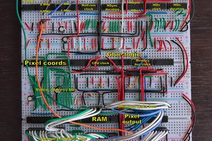
 matseng
Most impressive feat without a CPU.