I received my PCB for my Weather Base Station in record time; one week from China. It bugs me a bit that the boards cost $2 and shipping was $12, but $14 for 5 PCBs still seems like a deal to me.

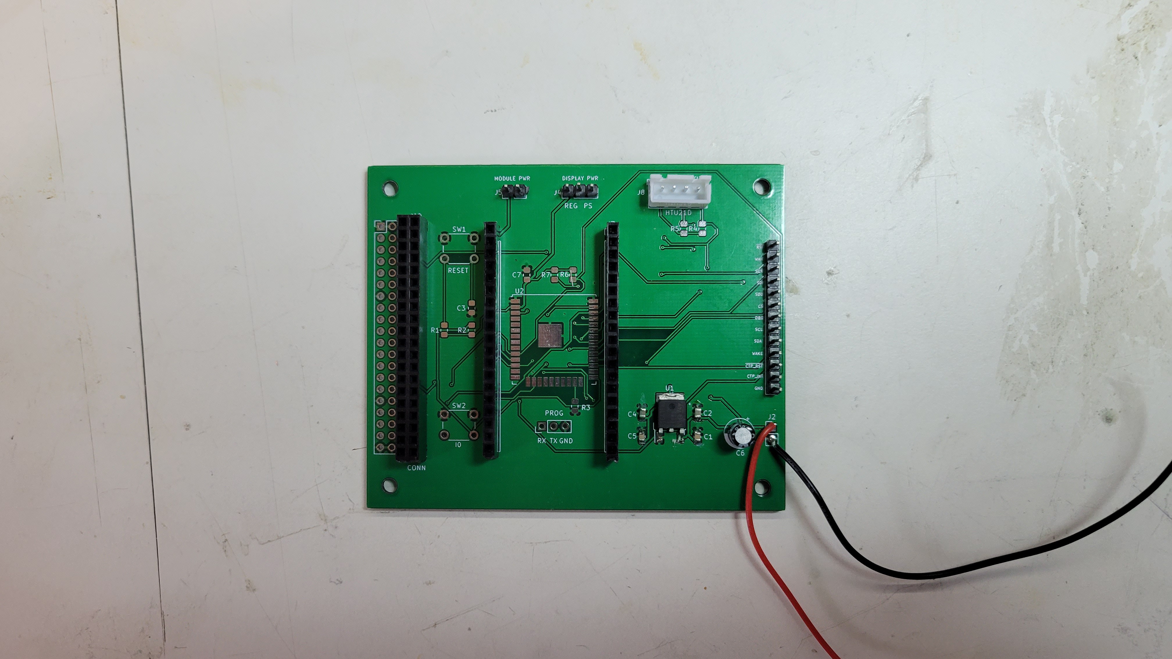
This is the PCB populated in my development configuration. The connector on the left attaches to the display connector, and the PCB sticks out to the right of the display for easy access to the test point connector on the right. There are a couple of jumpers which control where the ESP32 and display are powered, and a connector for an HTU21D temperature humidity sensor. The unpopulated footprints are for the "Production" mode, where the PCB will lie behind the display, and instead of an ESP32 dev module, an ESP32 WROOM 32U module will be used.

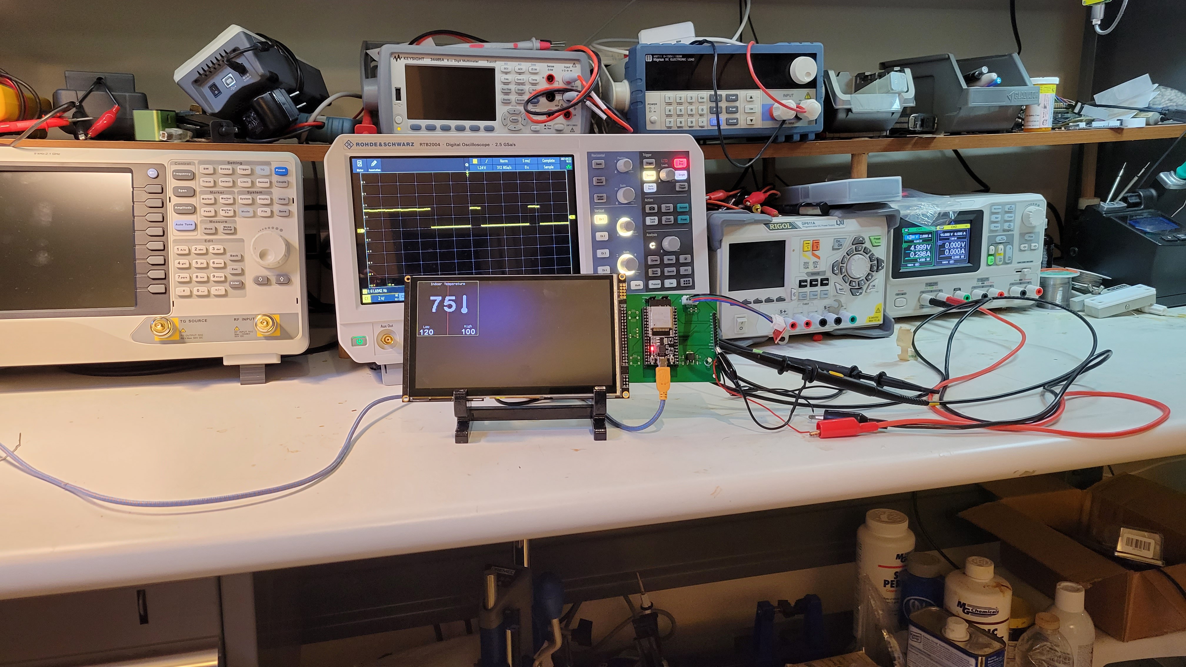
This is the development setup in use. As I suspected, the much cleaner layout of the PCB allows me to use the full 20MHz SPI frequency reliably. Here, the oscilloscope is probing the capacitive touch screen interrupt test point. The touch screen is the next thing I need to figure out, and will be the subject of the next log.
 Kevin Kessler
Discussions
Become a Hackaday.io Member
Create an account to leave a comment. Already have an account? Log In.