 Wriju
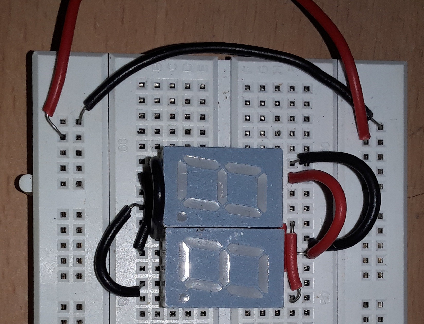
WrijuBuilding the prototype on breadboard. I connected two common anode seven segment displays to act as one multiplexing unit capable of displaying the two digits for hours and minutes alternately.
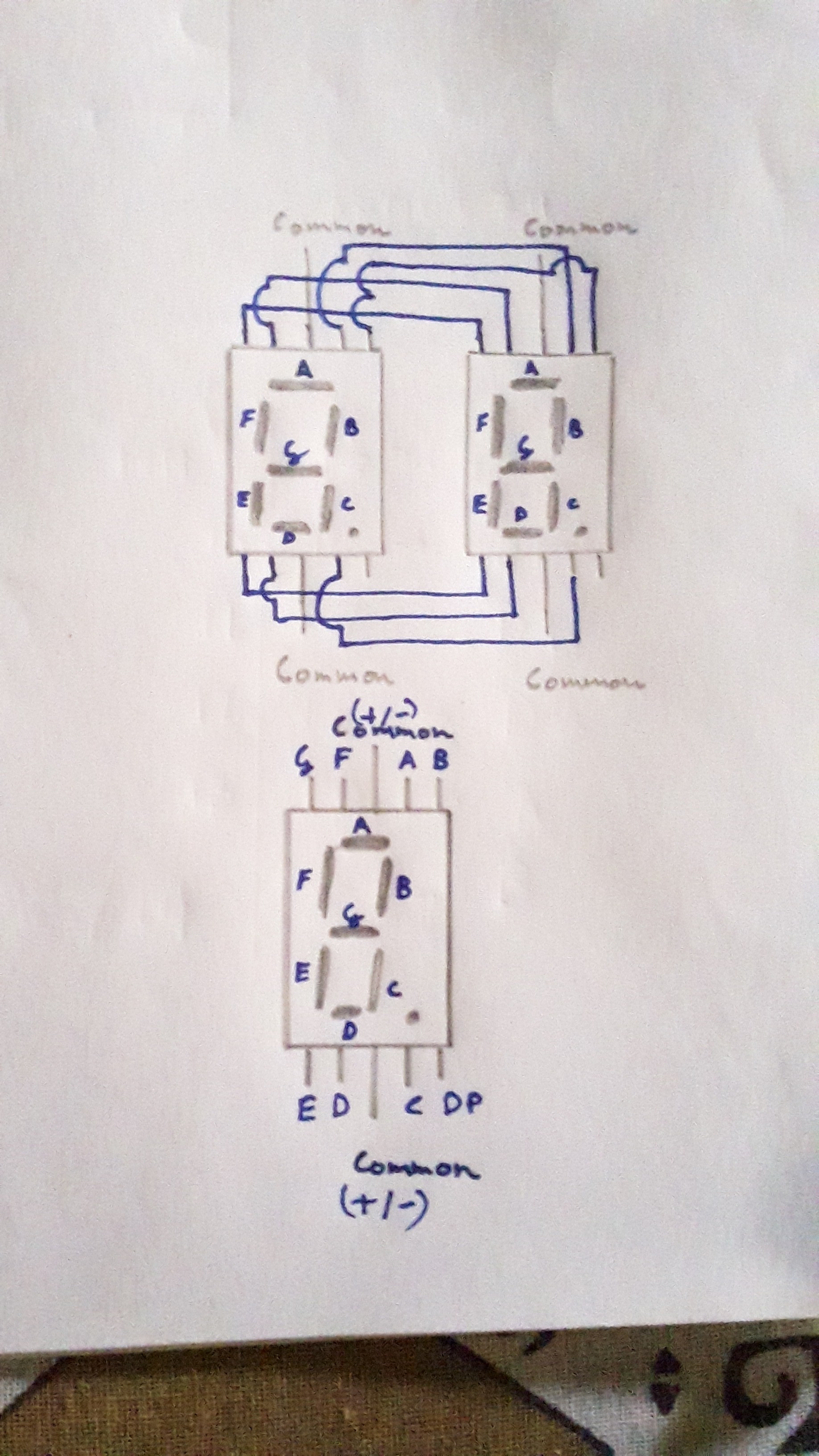
Two seven segments can be connected into a multiplexing configuration by connecting their corresponding segment pins together. This is exactly how the commercial multi-digit displays are made. The common pins for each display are left unconnected as these will be used for switching on or off each digit.
On breadboard the connections look like this
This is the schematic for the rest of the circuit.
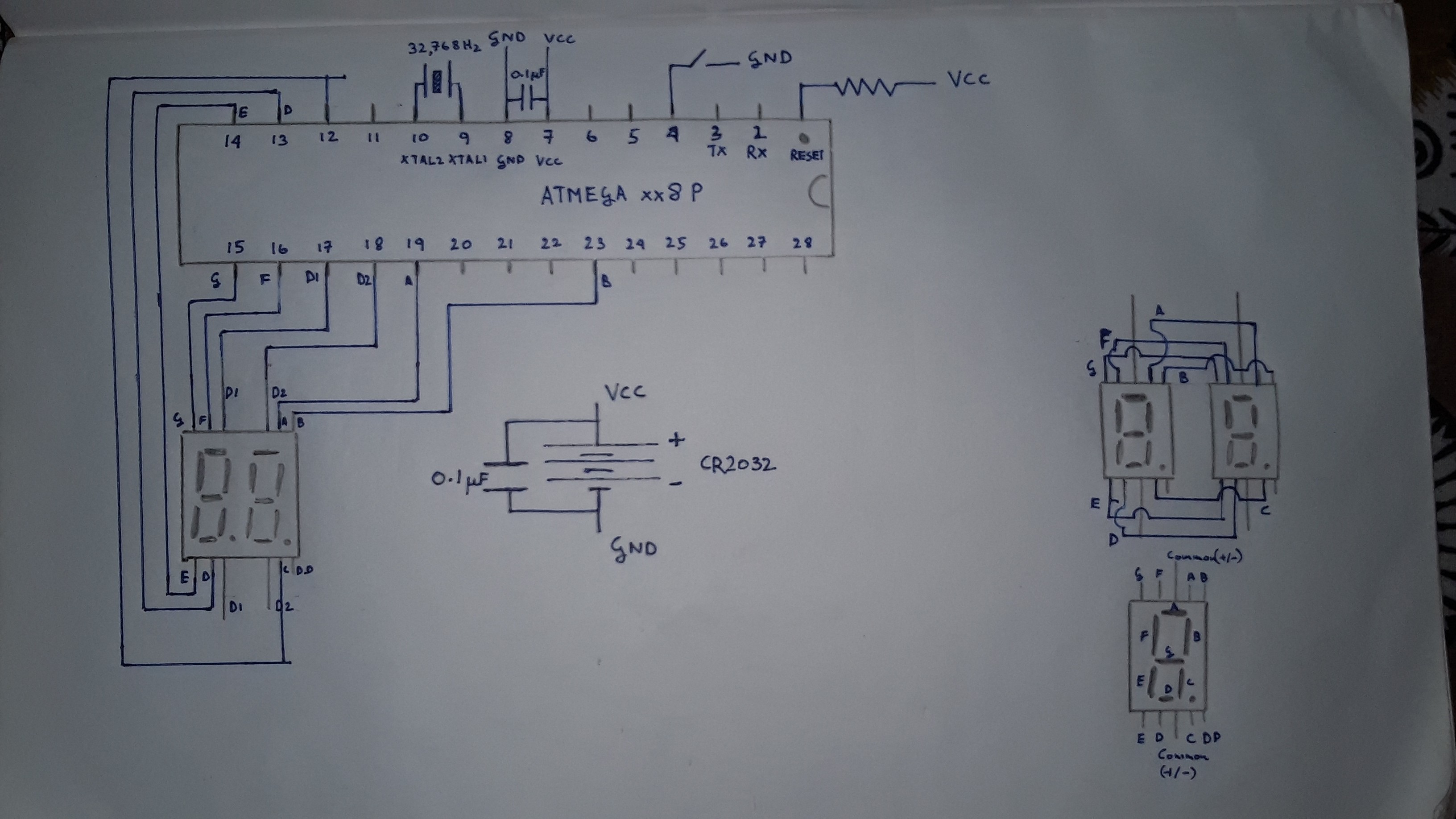
Yeah, I like to be generous with decoupling capacitors on my circuit.
You may have noticed that the watch uses only one button to change the time. This makes the connections a lot easier but it also means that the hours and minutes can only progress in one direction. Not so user-friendly.
After some troubleshooting (mostly faulty jumper wire connections), I got it working!
The video of breadboard circuit in operation can be found in the files.
Discussions
Become a Hackaday.io Member
Create an account to leave a comment. Already have an account? Log In.