 deʃhipu
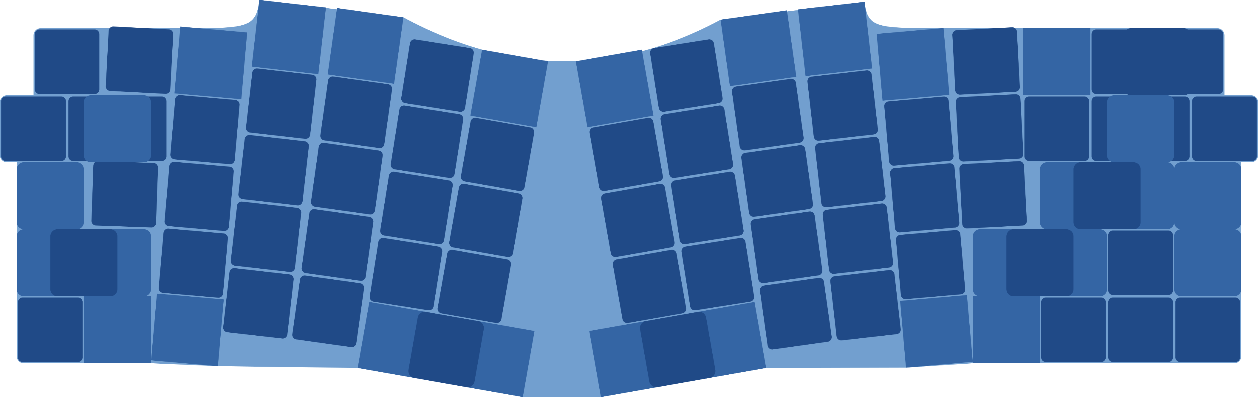
After exporting the layout as an SVG image, I started to work on a PCB for it. Putting a 0.75" square on top of some keys to see how they should actually reach, I got the basic shape:
Then I imported it in Fritzng, and put a switch footprint into each square, rotating them as needed. Then I exported it to SVG once more, to get all the holes for the sunken switches included in the board outline. Added diodes, SAMD21, and after roughly a day of routing we have the PCB:
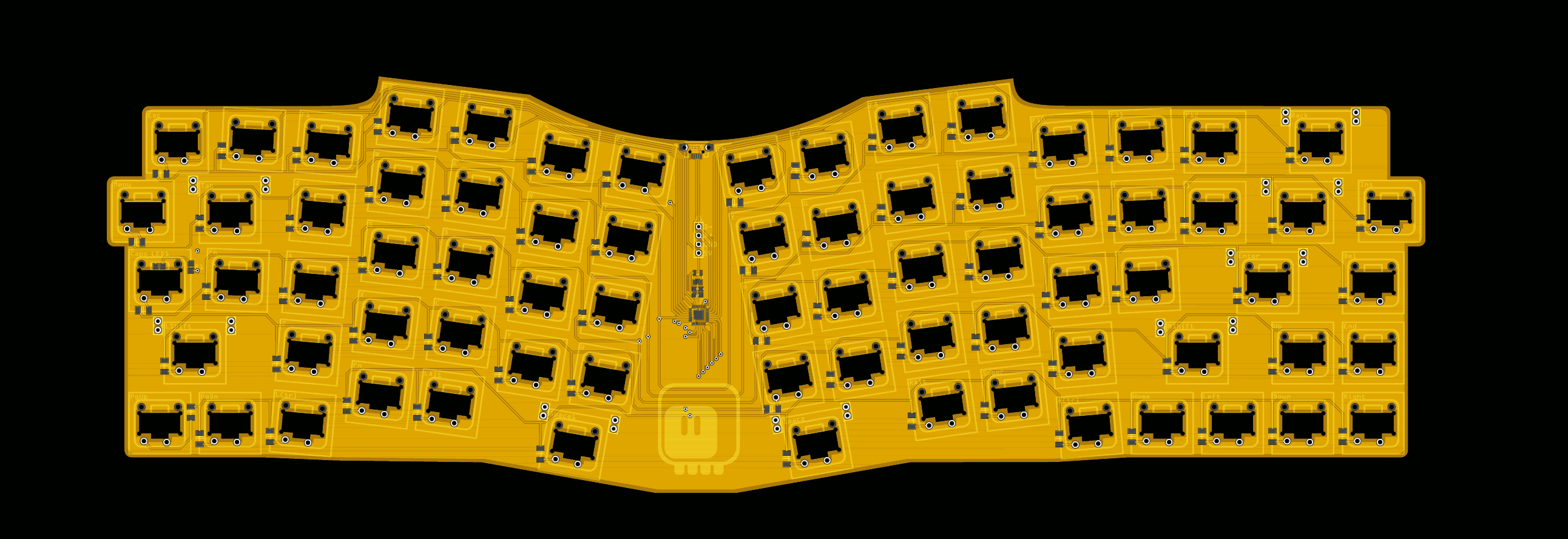
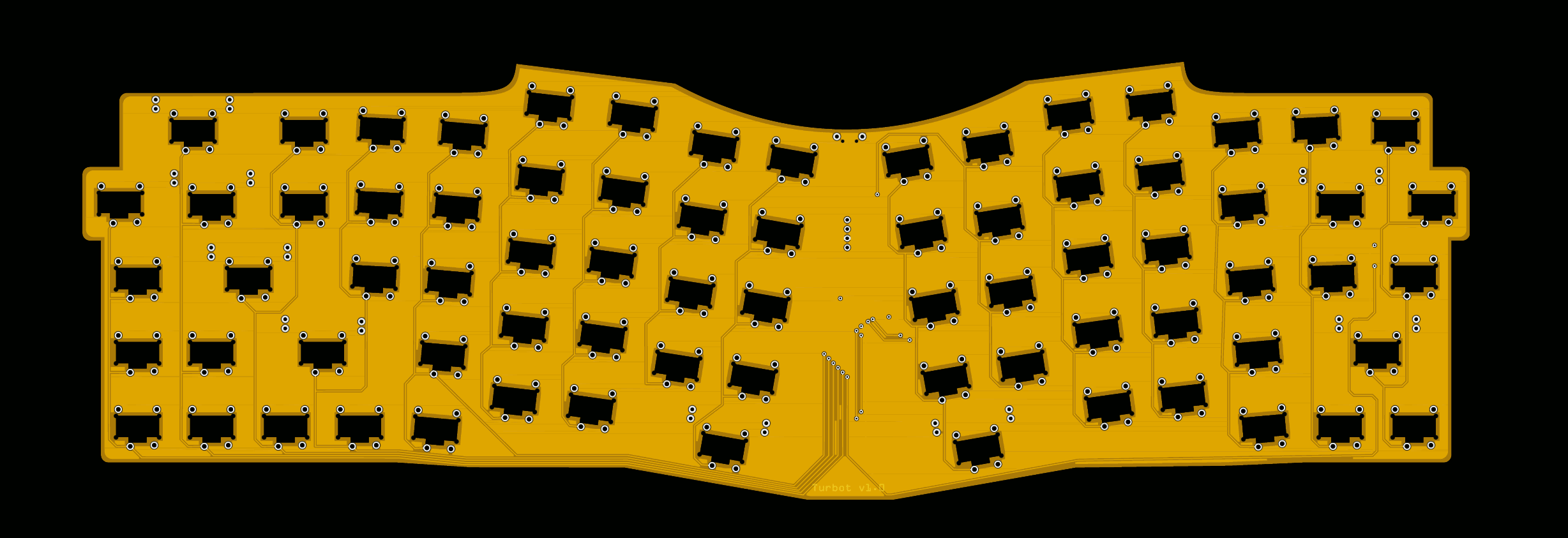
This is now ordered, so we will see in one week how well it came out.
Discussions
Become a Hackaday.io Member
Create an account to leave a comment. Already have an account? Log In.