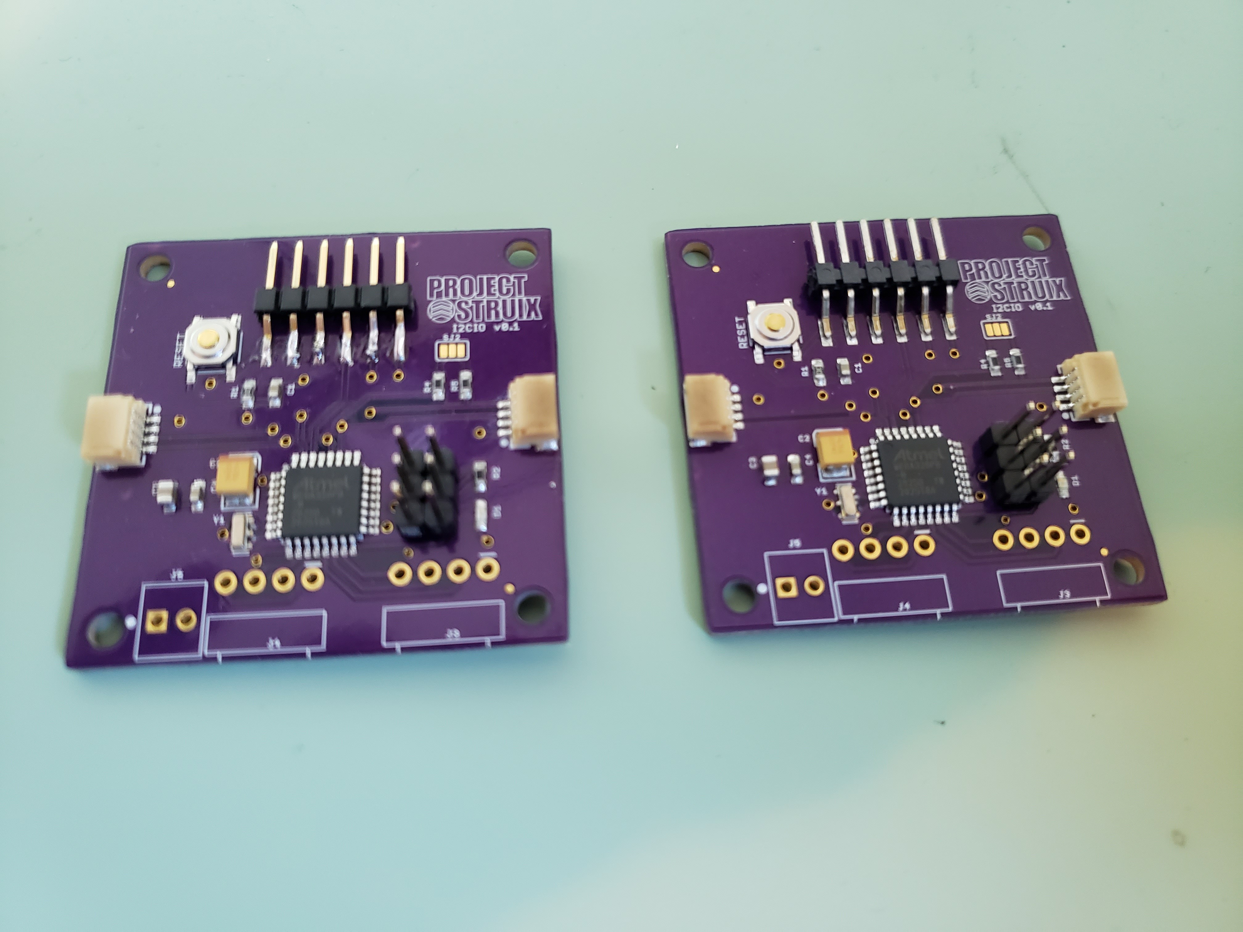
With the success of the first build, I finished stuffing and IR soldering two more I2C-IO. After programming and verifying the setup for Arduino, I'll hand solder the MOLEX right angle connectors and the terminal block used as a the external ground connection.
Notes to self on future builds:
- Use the black version of the JST (SM04B-SRSS-TB) "SH" series connectors used for the QWIIC I2C. The natural color tends to age and look a bit "roasty" from the exposure to IR in my SMD oven - even with Kapton tape. It's purely a cosmetic issue.
- Re-source and continue using the SAMTEC 6-position right-angle SMD connection headers with PCB locator pins. I used the last of those I had on-hand for the unit shown on the right in the above photo. The Harwin version (M20-8890645) without the locator pins will work in a pinch, however I like the finish I get by being able to solder in the oven. Takes the variability away from having to hand-solder.
I used an Atmel JTAG ICE-3 to program the 328PB's with the Arduino bootloader using Atmel Studio 7.
- Fuse settings are those used for the LilyPad Arduino board:
low_fuses=0xFF
high_fuses=0xDA
extended_fuses=0x05
- Bootloader (Found in the Arduino hardware files --> \hardware\arduino\avr\bootloaders\atmega)
ATmegaBOOT_168_atmega328_pro_8MHz.hex
That pretty well does it to program the board in Arduino.
Discussions
Become a Hackaday.io Member
Create an account to leave a comment. Already have an account? Log In.