 Tobias
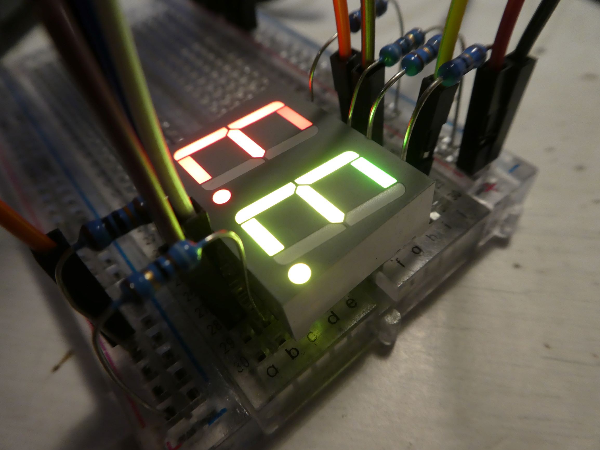
The story:
I like RGB things, and one of my friends was doing they're own freeform project (and they called it blinky), so I decided to to make a freeform clock. With an RGB seven-seg display because why not.
The 7 segment display
I was looking around for RGB 7 segment displays. Some people 3D print their own, but they're big and I don't have a 3D printer. I did some research on rgb 7 segment modules, an I found that the options were:
- Adafruit RGB 7-Segment Digit 1" (common cathode, 25 pins, super expensive)
- www.rgbdigit.com custom neopixel digit (digital, easy to use neopixel, semi-expensive)
- MIKROE 7-SEG RGB click (digital, "mikroBUS", ultra expensive)
- Sparkfun Dual 7-Segment Display RGB (multiplexed, difficult to use, cheap)
I chose the last one from Sparkfun. Probably should have chosen the digital addressable chainable and definitely much simpler one. But that would be too easy. Now I have 42 pins to connect with brass wires 144 LEDs (7 segs + dp * 3 colours * 6 digits) to multiplex. yay.
Microcontroller and other electronics
Since I was getting the 7 seg display from Sparkfun, I bought everything else for this project from them too. That includes an Atremis Nano dev board, because it is one of the cheapest for some reason. It features Bluetooth and tensorflow-lite voice recognition capabilities via the built in mic. We'll see if I end up using those. It also has a 48MHz microcontroller, and 21 GPIO. Because that's not quite enough pins to multiplex the 144 LEDs, I'll also be using the Sparkfun GPIO expander breakout for 16 extra PWM pins (very useful breakout BTW).
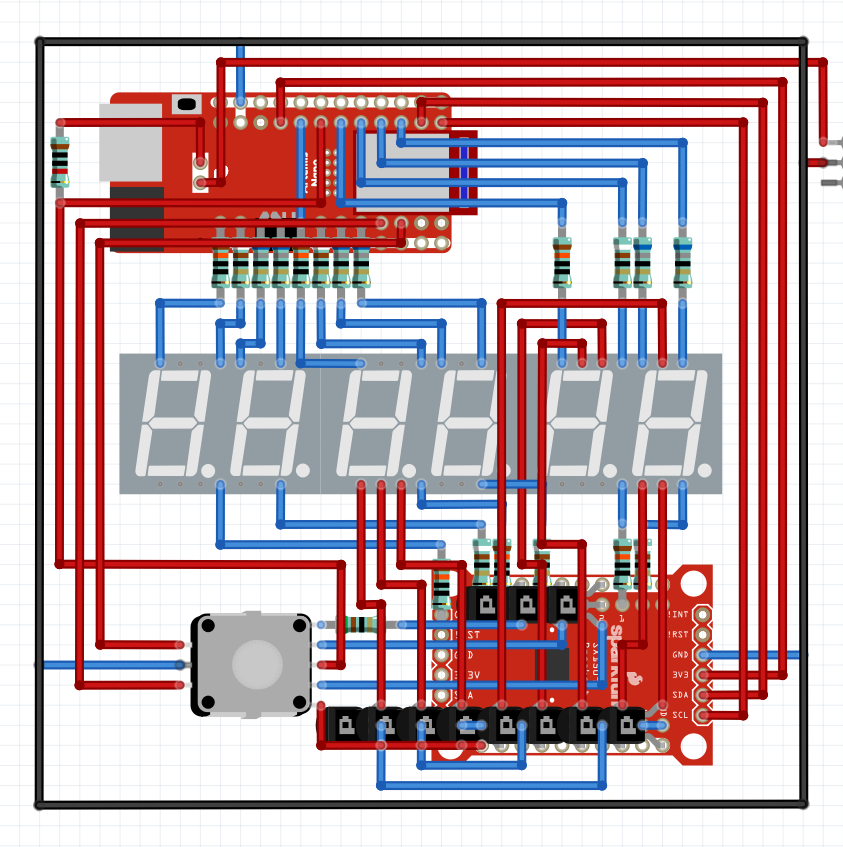
The plan:![]()

This is a thorough layout of all the brass wires, including to-scale circuit boards. This should be pretty much what it will look like in the end. This doesn't include all the wires to some of the anodes, because that would clutter and confuse he plan.
Current status of the project:
I'm building it. Slowly but also as fast as I can.
 This plan is a product of weeks of procrastination about actually getting started on the physical project.
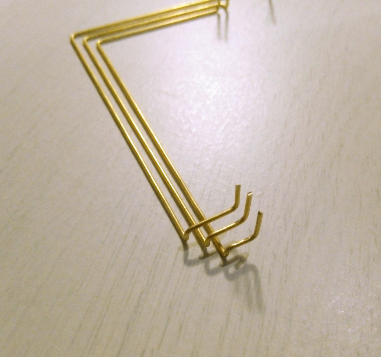 I'll post another update when I finish with the wire bending, and will hopefully have a soldering iron to finally assemble this project! Cya then!
 monte
monte
 Viva Penguinos