A Big bonus of JLCPCB.COM
The JLCPCB want offer 10 units of this Arduino compatible PCB for your projectsfor$2 in your first order with the link: Earn my PCBs Arduino Compatible.

1 / 2
Introduction
Generally in industries, we have several machines and equipment (PLCs, CNC, frequency inverters) controlling and monitoring the most diverse industrial processes.
For all of this equipment to work together, it is essential that there is a communication network between them.
However, the industry is an environment that suffers from the presence of many electromagnetic interferences due to the activation of motors, solenoids, and other actuators.
So the communication network needs to be robust, in view of this need, the RS485 communication standard was created.
The RS485 communication standard is the physical layer of the communication network, and several protocols such as Modbus, Profibus, and others can be implemented.
The RS485 communication standard is suitable to be implemented in the industry, as it accepts several network topologies such as Star and ring, for example.
It allows communication over long distances and uses twisted pair cable. This cable model reduces electromagnetic interference since we have a differential communication signal and this contributes to being more immune to noise and electromagnetic interference.
In addition to RS485 communication, there is also RS232 communication. It allows network communication in point-to-point mode and suffers more from electromagnetic interference.
However, many devices have RS232 communication and need to transmit data over long distances. For this, we need to use the integrated circuit called MAX485.
This integrated circuit plays a role in adapting the TTL logic level to the logic level required for RS485 communication.

Figure 1 – Integrated Circuit Max 485
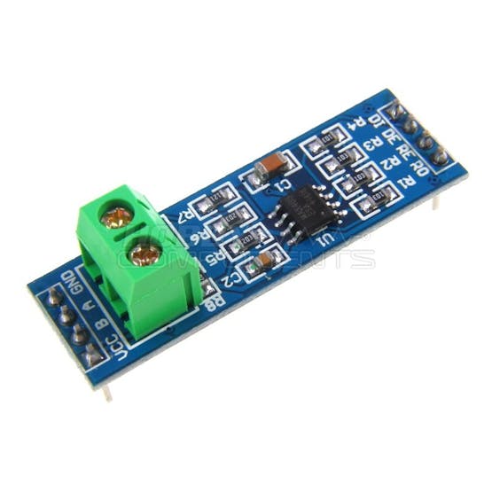
Nowadays there are already ready and low-cost modules with this integrated circuit. They allow signal conditioning and facilitate communication between different equipment.

Figura 2 – RS485 Module
Thus, RS485 communication can be used in any type of environment due to its robustness.
So in this article, we will learn how to monitor the temperature of an environment and receive the measured value through serial / RS485 communication between two Arduinos.
The Arduino Slave (Transmitter) will perform the temperature measurement using a DS18B20 digital sensor and will send this measured value via serial / RS485 to the Arduino Master (Receiver) that will write on the LCD display 20 x 4 I2C the received temperature value.
Therefore, through this article you will learn:
- Perform the circuit assembly on the protoboard;
- Understand the operation of the RS 485 module;
- Understand how the DS18B20 sensor works;
- Create a communication protocol;
- Carry out remote temperature monitoring using a wired communication network;
- Earn your own Arduino Compatible Board of the JLCPCB.
Now, we will start the complete presentation of the development of the project Temperature monitoring with the DS18B20 sensor using RS485 serial communication.
Developing the Temperature Monitoring Project with the DS18B20 sensor using RS485 serial communication
In figure 3 we have the schematic circuit necessary for the assembly of the project.

Figure 3 - Schematic circuit required to assemble the project.
The Arduino Uno will be the master (receiver), it will receive the temperature measurement and will display on the LCD display 20 x 4 I2C.
The Arduino Nano will be the slave (transmitter), it will read the DS18B20 sensor and send the measured value through the RS485 module.
Now let's go to the list of materials needed to set up the project.
The Project with DS18B20 and RS485 Module for Arduino
The temperature sensor DS18B20 is a digital temperature sensor, because to transmit the information it uses the protocol...
Read more »