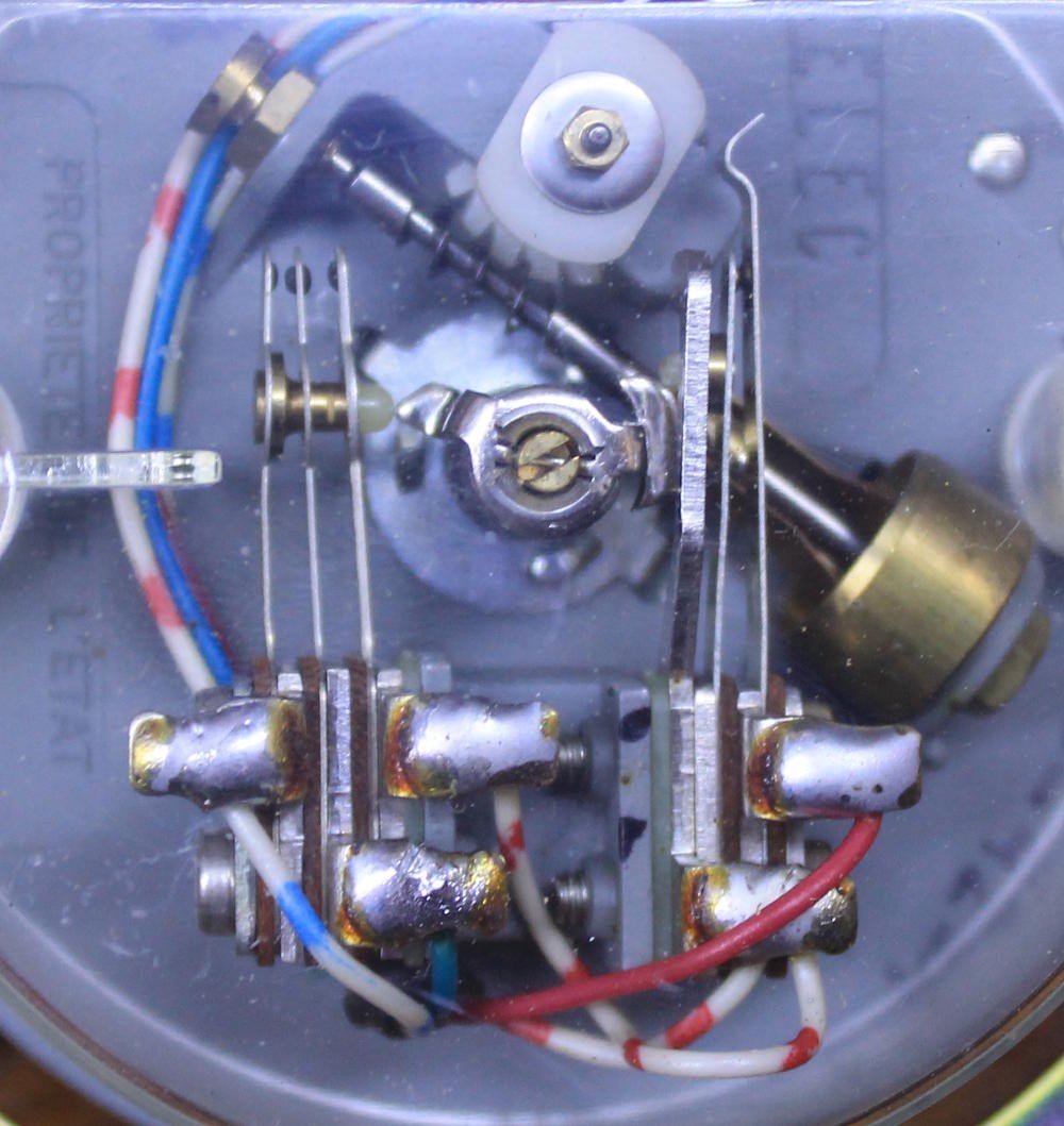
The phone I use contains a dial with a series of contacts but only 4 wires.
- Blue
- Blue-white
- Red
- Red-white.
The mechanical system is more complex however. Here is how it looks when at rest:
- The left group detects when dialing occurs. It has 2 contacts that are normally open and connected to the blue wire.
- The right group generates the pulses, with a normally closed switch, connected to the red switch. It is however forced "closed" at the end of the rotation.
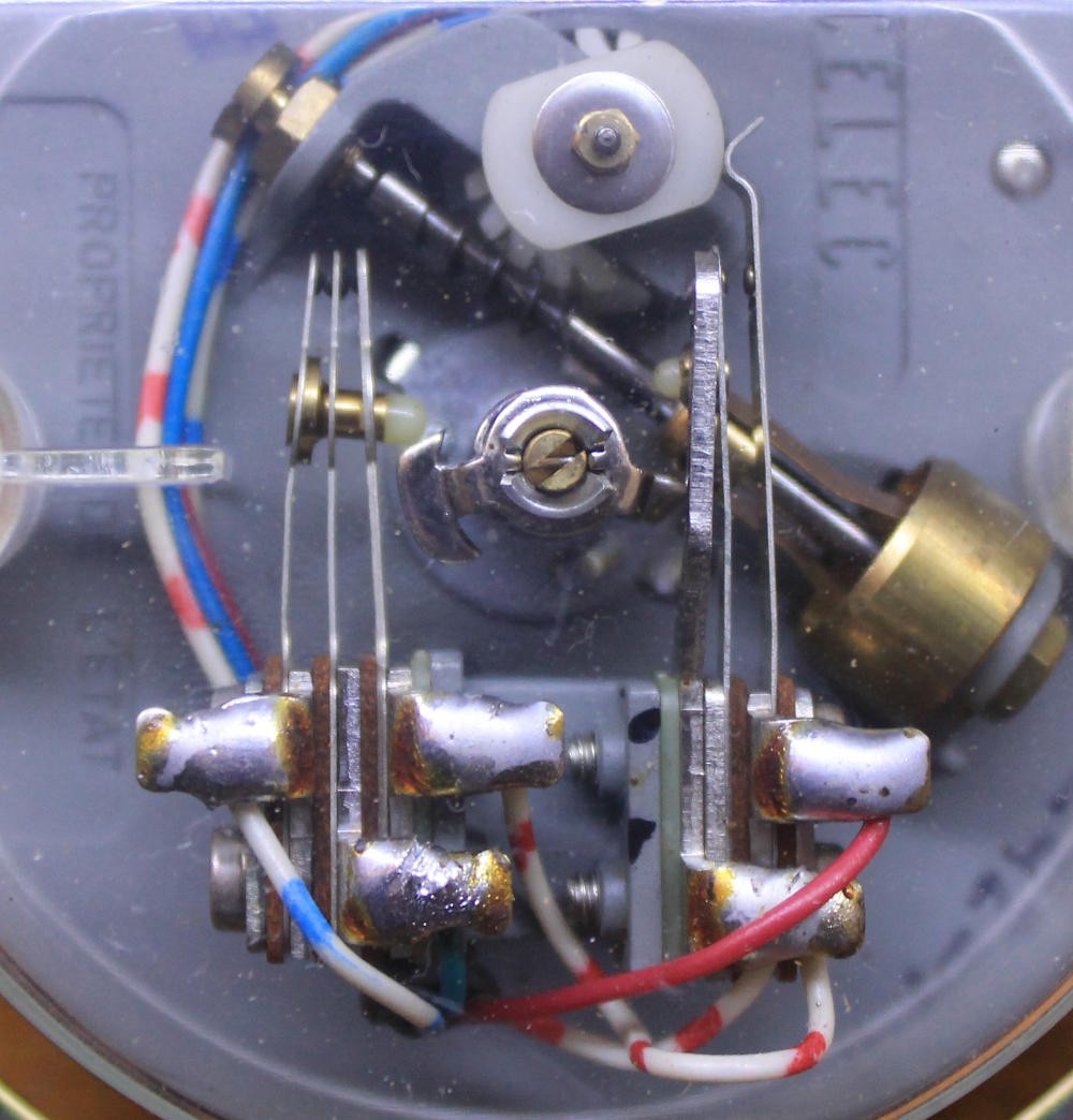
Here is how it looks during dial:

The most interesting feature/trick is how the left group steers the signal for the right group, because the red-white wire is connected to both.
The Blue wire is in the middle contact, blue-white on the left and red-white on the right. The spring mechanism ensures that the Blue/Blue-white (right) contact is closed before the Blue/Red-white contact when dial begins, and after when the rotation ends. So Blue is closed during operation.
This is easily verified with a multimeter but a problem arises : the signal does not look clean. There is a high resistance when I can get it to work and a drop of at least 100mV so this contact needs cleaning. Which might explain why this device was discarded after more than 40 years of existence...
Scratching the contacts restored the current. The system is stored in "open contact" position so it would oxidise with time. OTOH the Red/Red-white contact is normally closed and the contact is good (very low resistance) so the signal is quite clean.
Through the Red-white link, both sides are connected and Blue-white can be substituted to Red-white in the tests (when the contacts are clean).
- Blue-white is the common contact
- Blue is the dial signal
- Red is the pulse signal.
Testing is believing !
.
 Yann Guidon / YGDES
Discussions
Become a Hackaday.io Member
Create an account to leave a comment. Already have an account? Log In.