On and off, I had been experimenting on this but with very little success.
There are too many unknowns and trying to guess how it works by modifying the code and reprogramming the flash could be too time consuming.
Later, I came up with the strange idea of connecting the vacant flash pins on the board to another microcontroller and have this microcontroller pretend it is some form of flash.
How I did that:
- Soldered the vacant flash pins with 1.27mm pitch ribbon cables (22 pins each),
- Taped the soldered wires with the Kapton. The lines on the PCB are very, very flimsy and could not tolerate a lot of movement at the solder points!
- and connect two female IDC sockets (more than 22-pins) on the other end of the wire (not shown here):
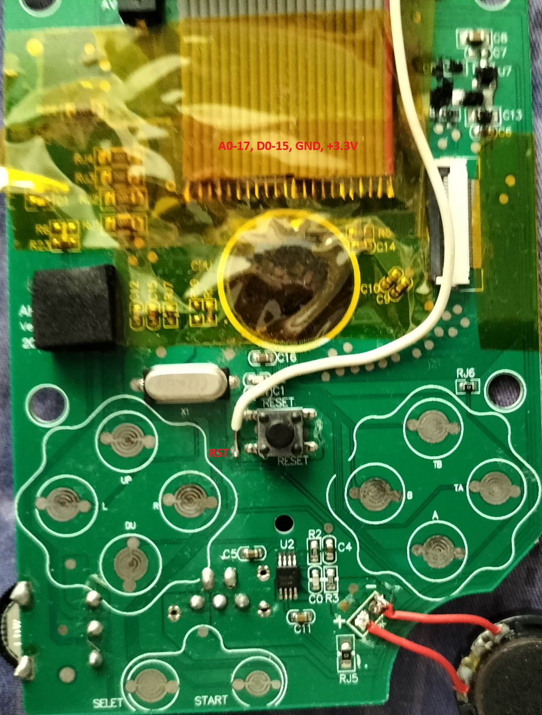
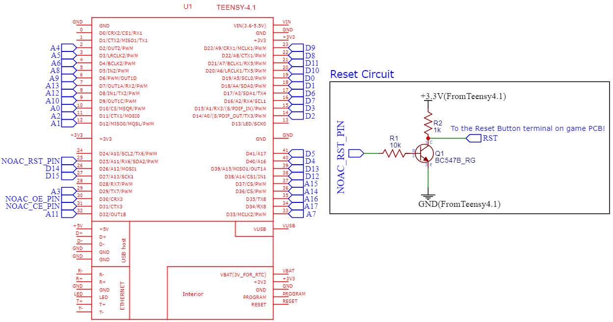
Oh, and a lot of jumper wires to connect this back to the Teensy 4.1 from the end of the female IDC connector . Here is the rough schematic (also note the white cable connected on the Reset Pin which is the "RST"):
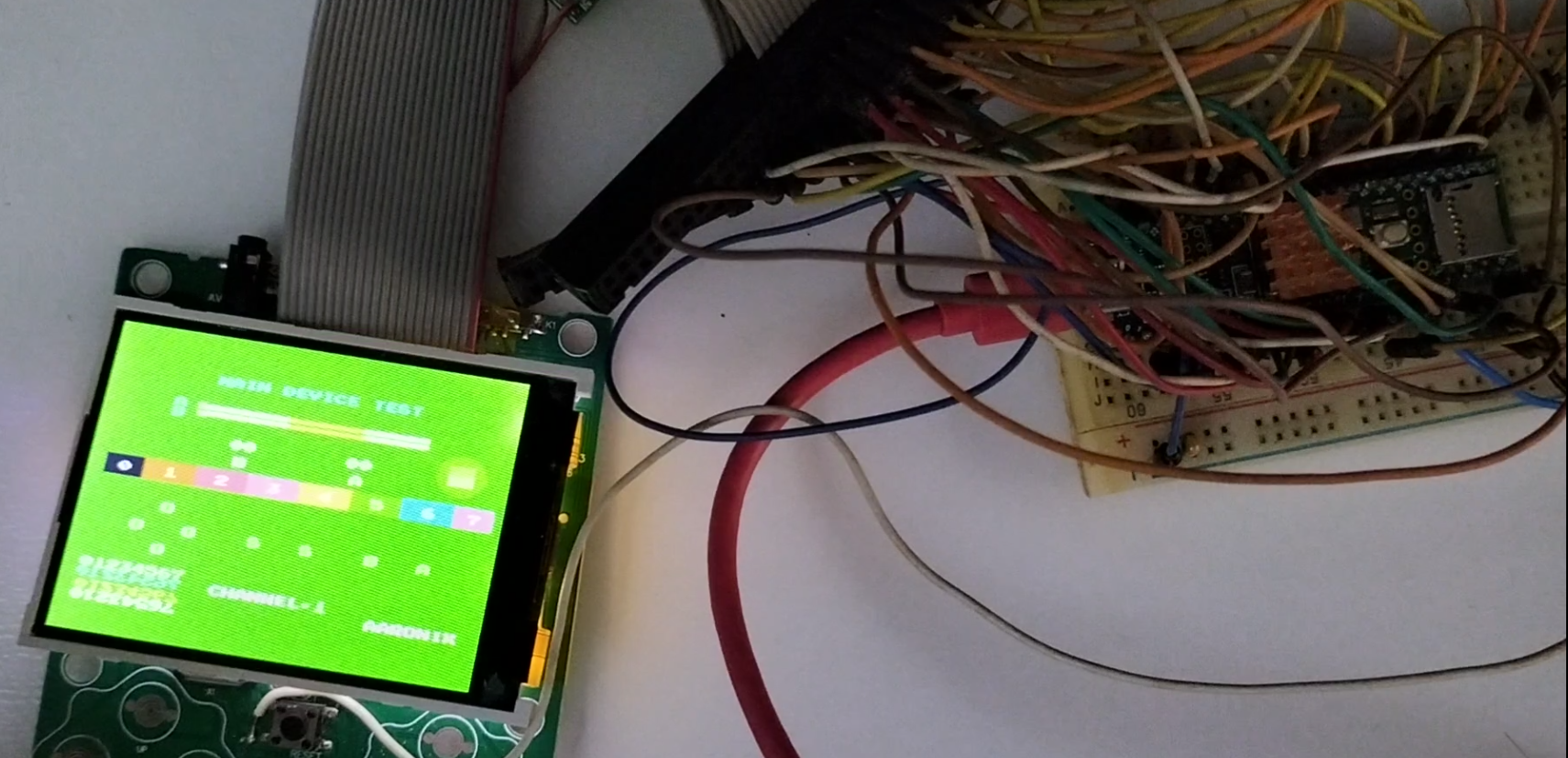
It should be something like this in the end (pardon the mess! I will draw another cleaner diagram for this one!):
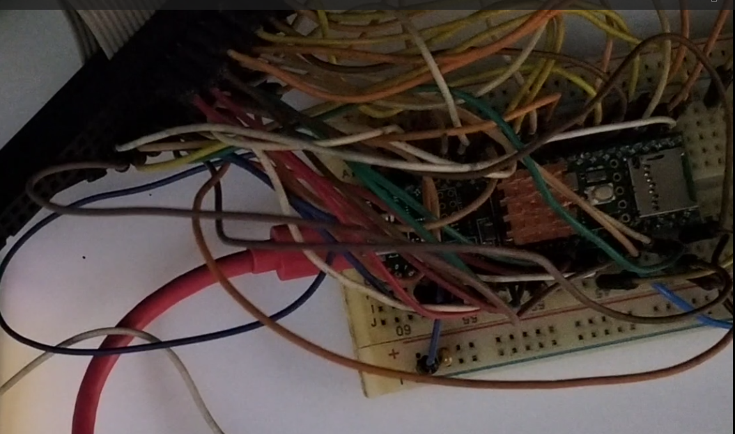
Well, all the pins are connected. Looks frustrating, and I got it done after a few weekends on this!
What would ever happen if I program the Teensy to manually feed the whole game board some instructions?
Discussions
Become a Hackaday.io Member
Create an account to leave a comment. Already have an account? Log In.