You may have heard of the Second System Effect where the second revision of a successful project becomes bloated on rewrite. I suffer from the First System Effect where I put features in just in case but that turn out to be not used or too cumbersome.
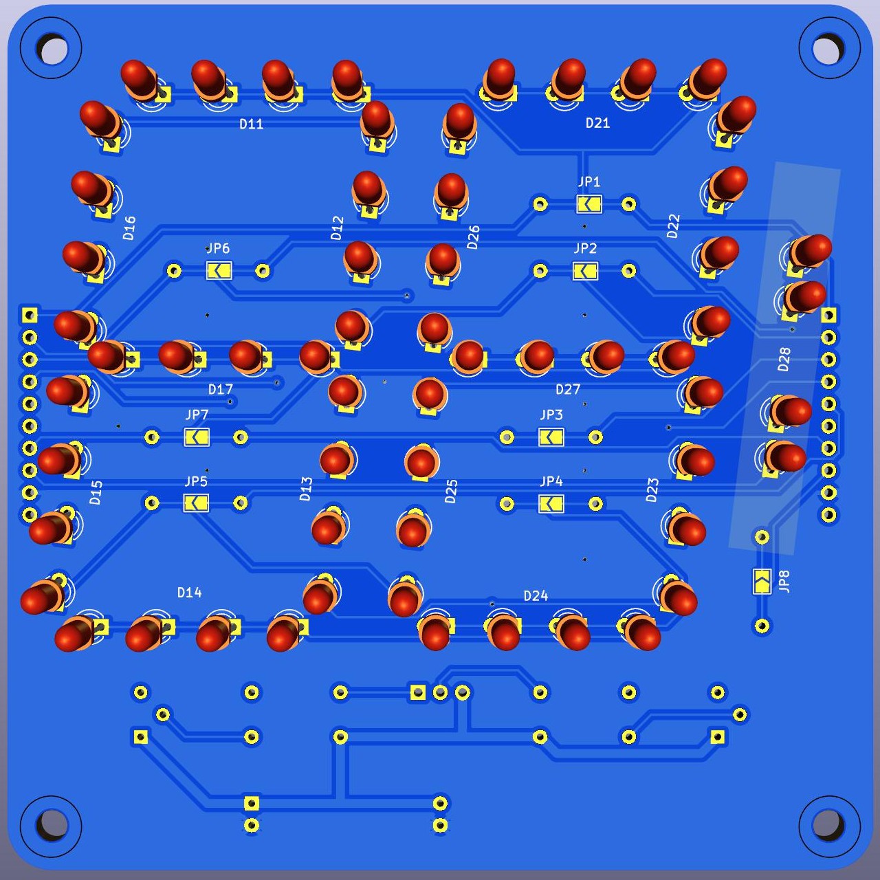
The first version of this display board worked as expected but there were shortcomings with it. So I have trimmed the features that weren't useful.
- Get rid of constant current diode, never used.
- Get rid of 6 pin anode daisy chain connectors, use individual anode drive lines. The anode drive lines don't warrant daisy chaining.
- No more cathode drive transistors, installed elsewhere. LED current limiting resistors reduced to 7 or 8. Use solder jumpers to select between first and subsequent boards. In the first version I used wire jumpers in several places.
- As a result reduced the 10 pin cathode daisy chain connectors from 3 to 2.
- Cathode drive inputs moved to right edge of board freeing up space.
- Use wire stitching instead of connectors to join boards, flexure is not a big problem, metal clips or external mounts can provide support.
- Blue soldermask for better contrast.
I was inspired by a recent redesign of #89C52 clock board Incidentally I noticed that this project is still marked ongoing. I'll change that to completed. Although I'm still awaiting delivery of this new design, I don't expect issues as the circuit is simple.
 Ken Yap
Discussions
Become a Hackaday.io Member
Create an account to leave a comment. Already have an account? Log In.