 pcadic
Genesis of the project.
This project started last week (10/10/2020) when I saw the tweet of @kongduino playing with an old calculator. I always wanted to design a PCB-clone to have the opportunity to replace the old board of a calculator. I wated to learn the technic to re-engineer a board.
Step 1: Choosing and getting the calculator. After a ling search over the internet , I found a strong old computer. I was seeking a device with a strong box, a strong KB, easy to open. I also needed to make sure the keyboard has enough keys to handle a true PC keyboard mapping. I also needed a joystick for the ones who will want to use retropie.
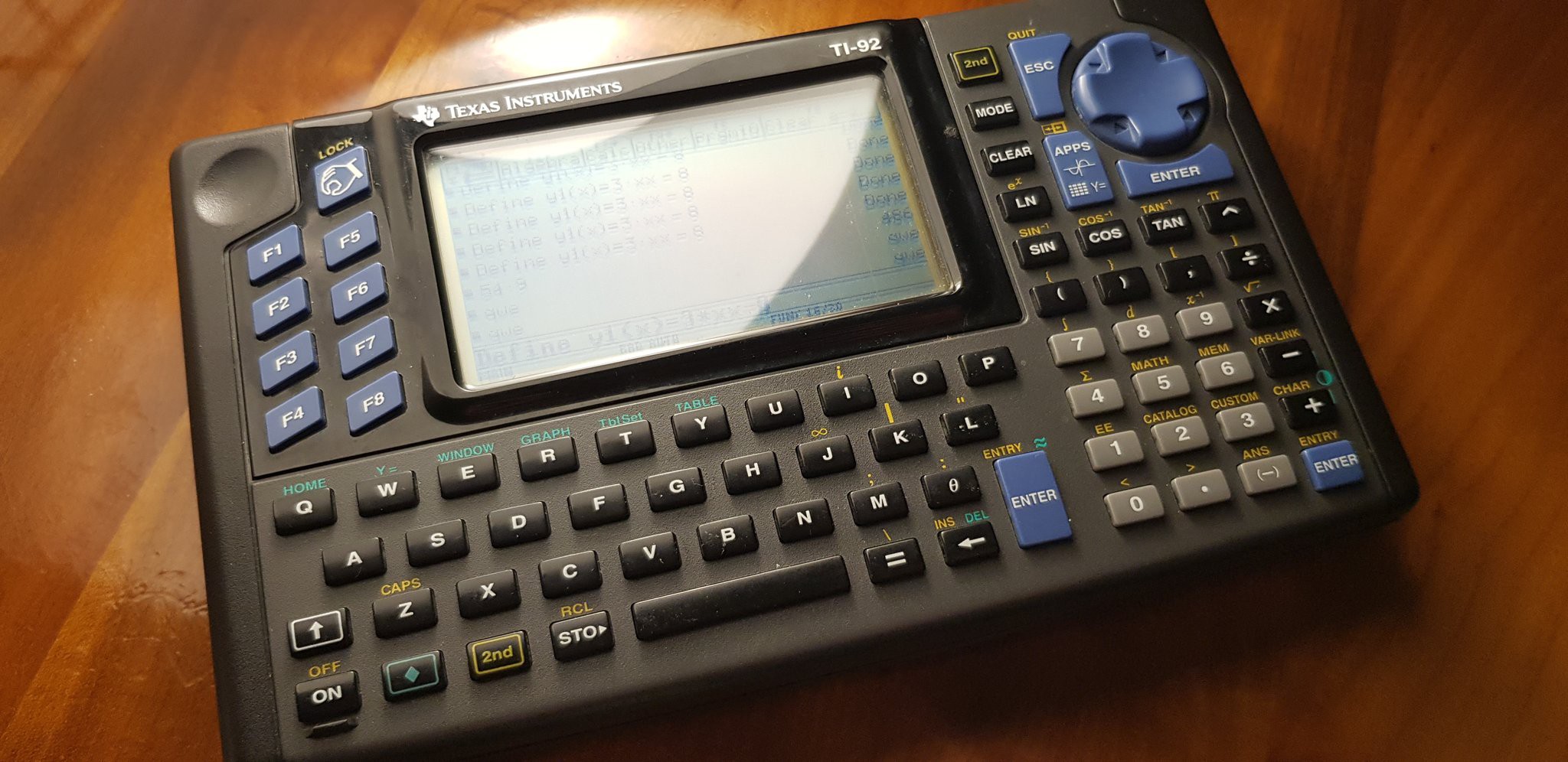
The calculator was found on ebay.fr for 39 € including shipping.
Phase 1
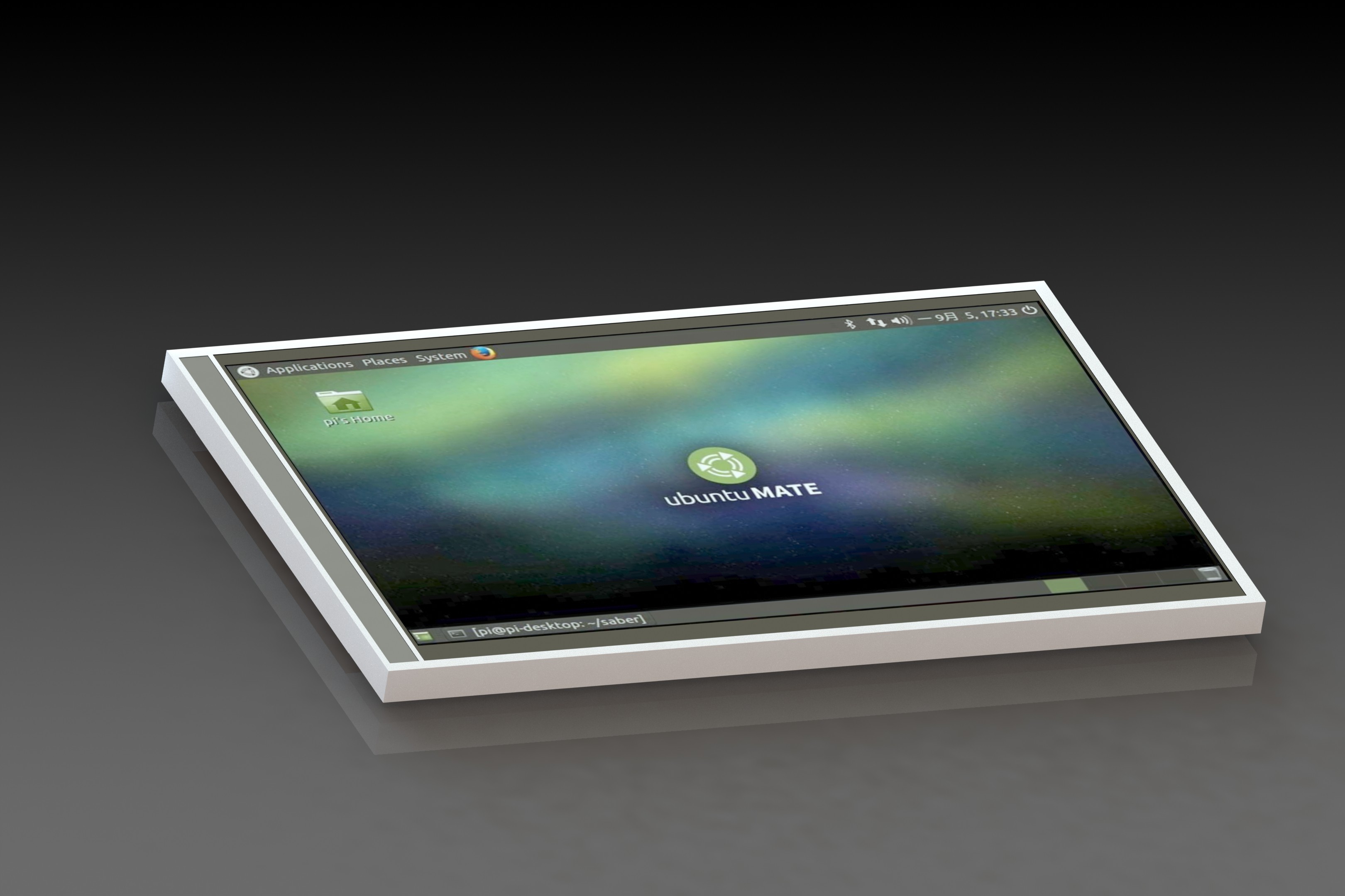
Finding the display. The old B/W display is crap. We want a good one with high rez and color. We found a ST7796s model with the exact same size on aliexpress.
Phase 2
The next step was to be able to get a JPG scan of the original PCBoard. This was done opening the case, removing all the thick components to get a plane and easy to scan surface.
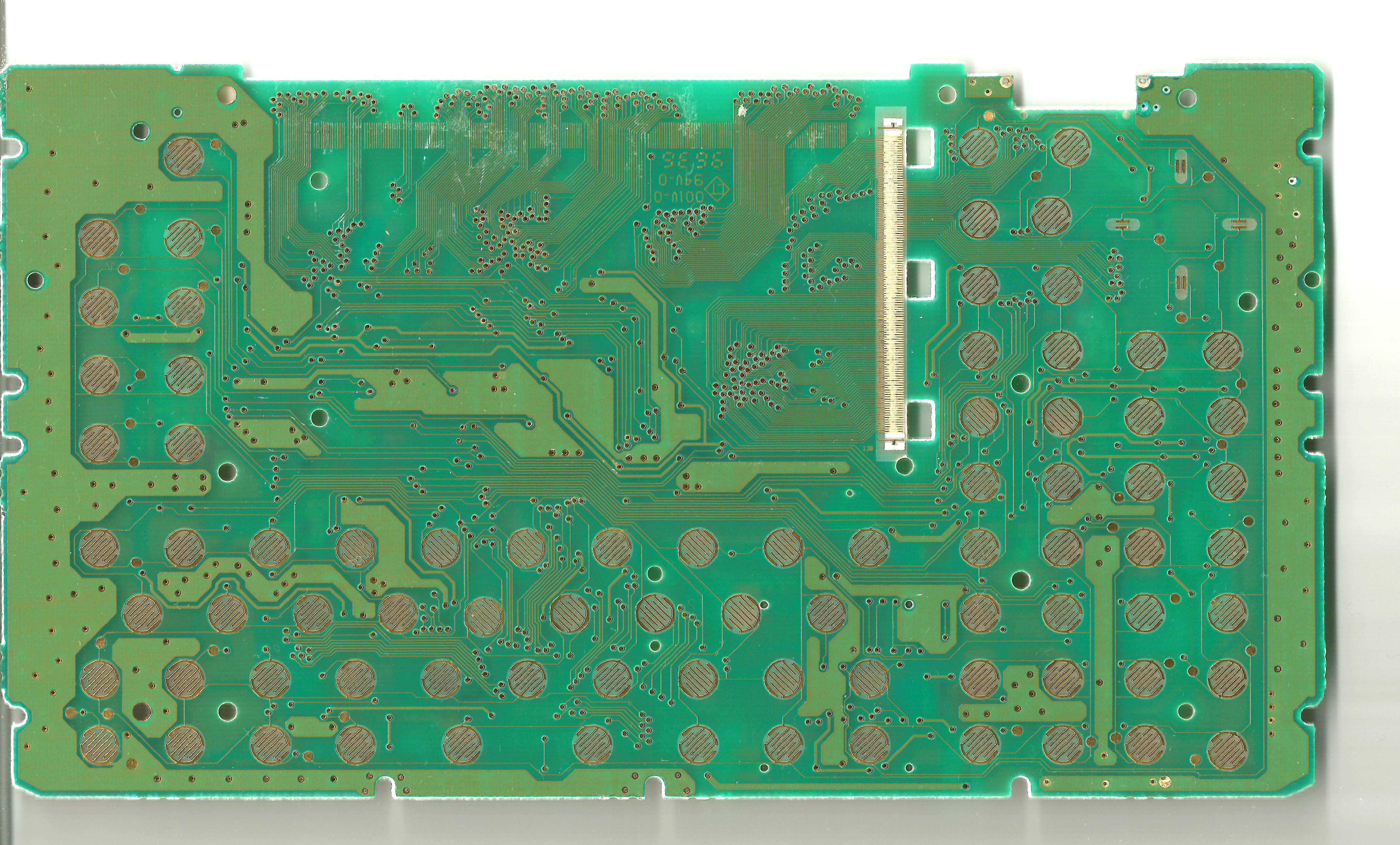
Once scanned, we imported the file into solidworks to resize, get the the contouring set, localize the key contacts, locate the drill holes. (You have all the files in our github) .
A cool feature of solidworks is to be able to save to DXF files. We did this and were able to import the DXF into KICAD PCBNEW software. Once done, the next step was to differenciate the EDGE.CUTS from the buttons footprints.
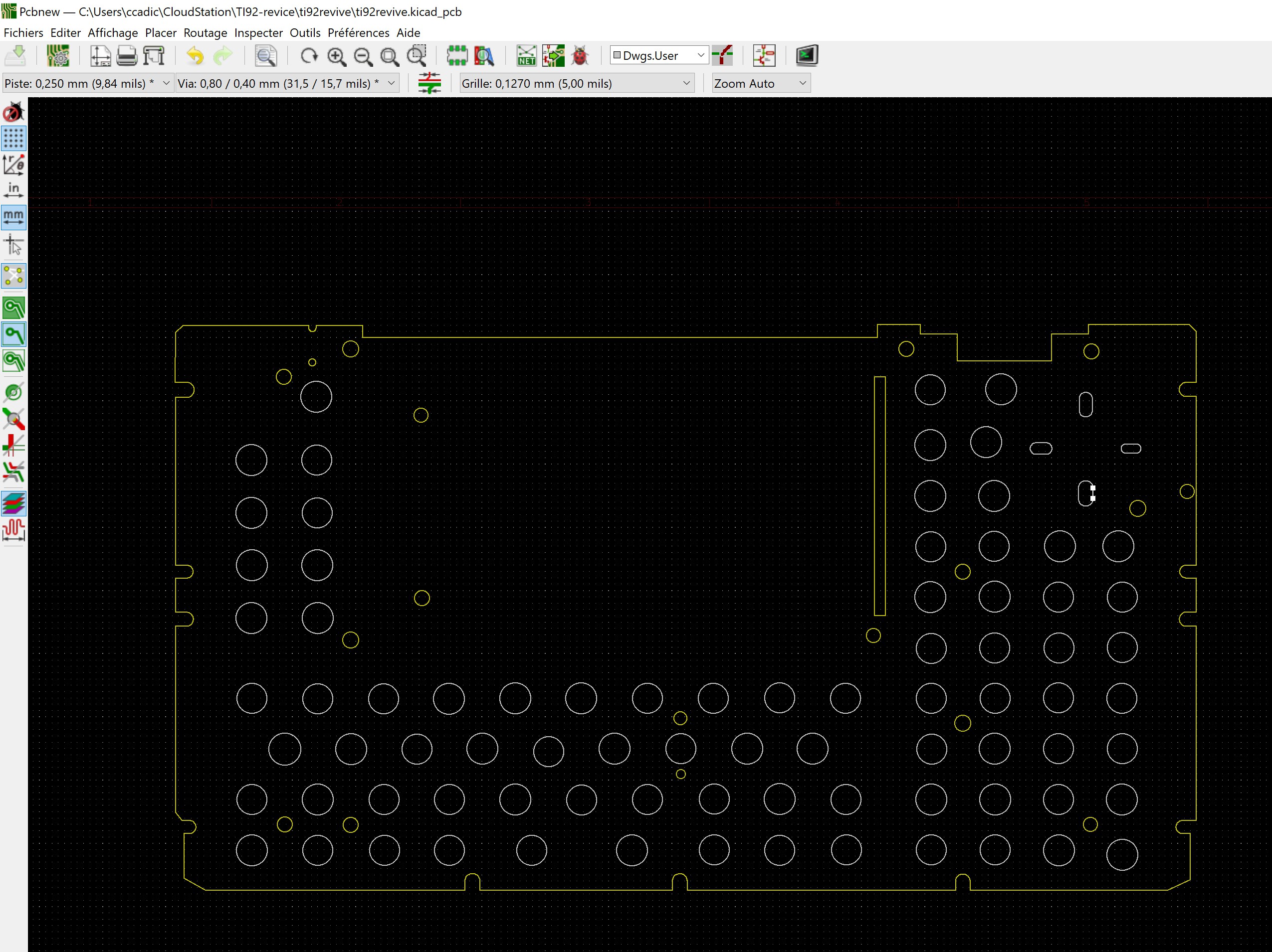
It is now super easy to re-use the template with your own project.
Discussions
Become a Hackaday.io Member
Create an account to leave a comment. Already have an account? Log In.