There was a little pause because we had holidays and went on vacation so I missed the last full moon (20220318), but there are plenty of parts left.
Soldered Nr. 7 today - 20220320 - 18:27
One resistor (the 360R one) didn't sink into the solder on one side, resulting in an open connection. I'll generously count this as the first tombstone in this experiment:
Since I have a second sample now, it's probably time for a table to keep all those exciting results nice an tidy.
Time needed for each phase of assembly:
Set up jig and apply paste: 3:30
place parts: 8:30
reflow: 3:00
Total of about 15 minutes for the top side. I'll have to create a little helper for the battery holder because it has no alignment pins, and that's a bit unfortunate. Cardboard might not be the best choice here because it might get a bit too hot during soldering.
In a way, I knew this already - but lifting the stencil after paste application is one of the seemingly simple steps that can mess up all the work you put into alignment and spreading the paste. If the stencil is flat on the board / work surface, it's almost impossible to lift it without shifting.
Since I'll be making many of these boards I decided to create a little jig. What we need:
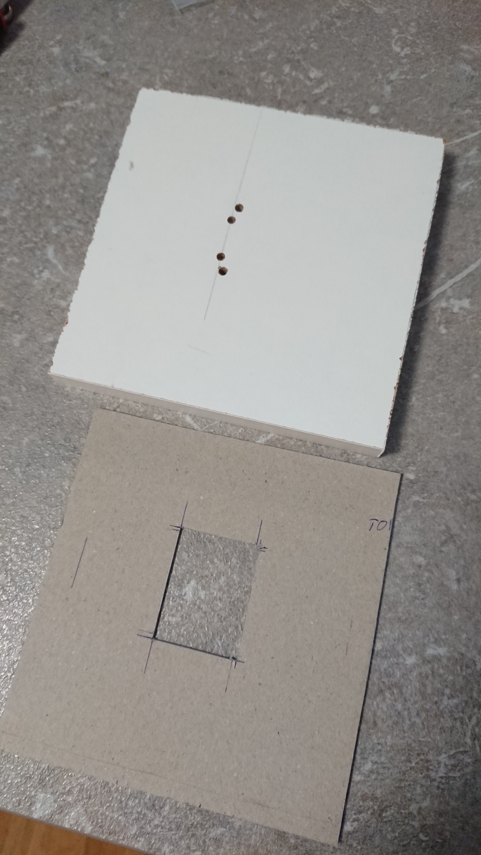
a piece of smooth (sealed? don't know what it's called) chipboard
a piece of cardboard with the same thickness as the PCB
the alignment pegs I had shown in an earlier log
glue
The chipboard is drilled to make room for the pegs and a pair of screws, and the cardboard gets a cutout for the PCB:
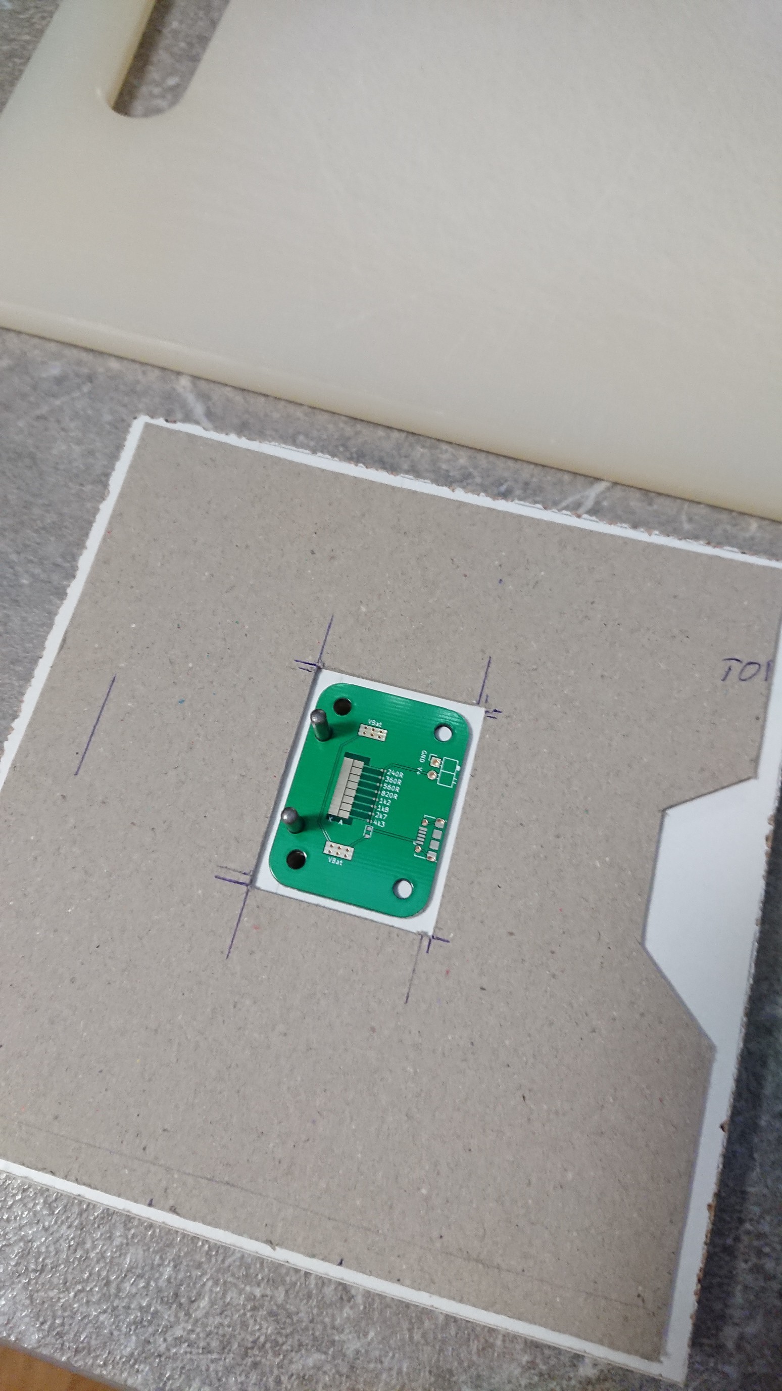
Then I though about the lifting problem described above, and added an extra cutout before gluing it to the chipboard. Here it's shown with PCB and pegs:
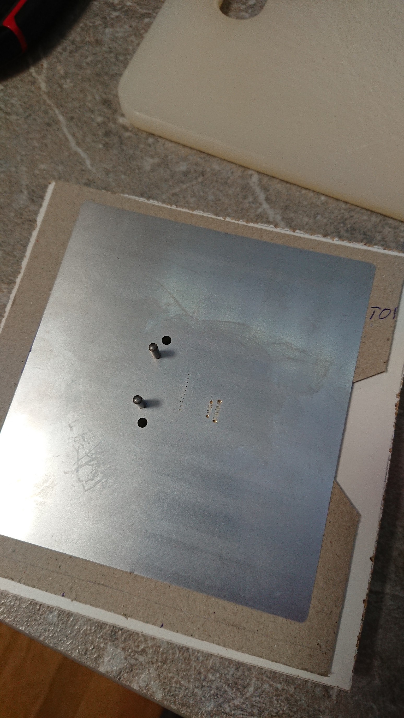
And now with stencil - still aligns very well:
When paste application is done, I can hold down the stencil with a finger, remove the pegs and lift the stencil without harming the paste job.
There's still one major drawback: When the pegs are removed, nothing keeps the PCB from shifting because the cardboard isn't fitted tightly. Maybe next time.
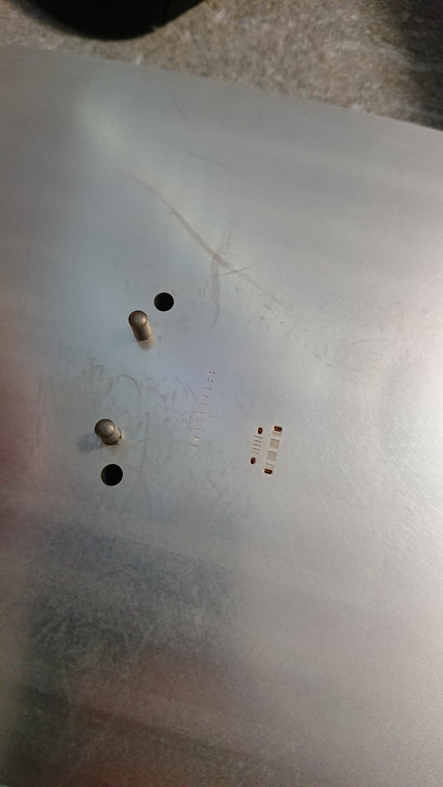
Aligning stencil and board with pins works really well (I know this is quite common but it's the first time I tried this, and also my first boards and stencil from JLC):
All went well (unfortunately?) for the first one:
This board was done on Jan 17th 2022, reflow started at 21:03 (almost full moon).
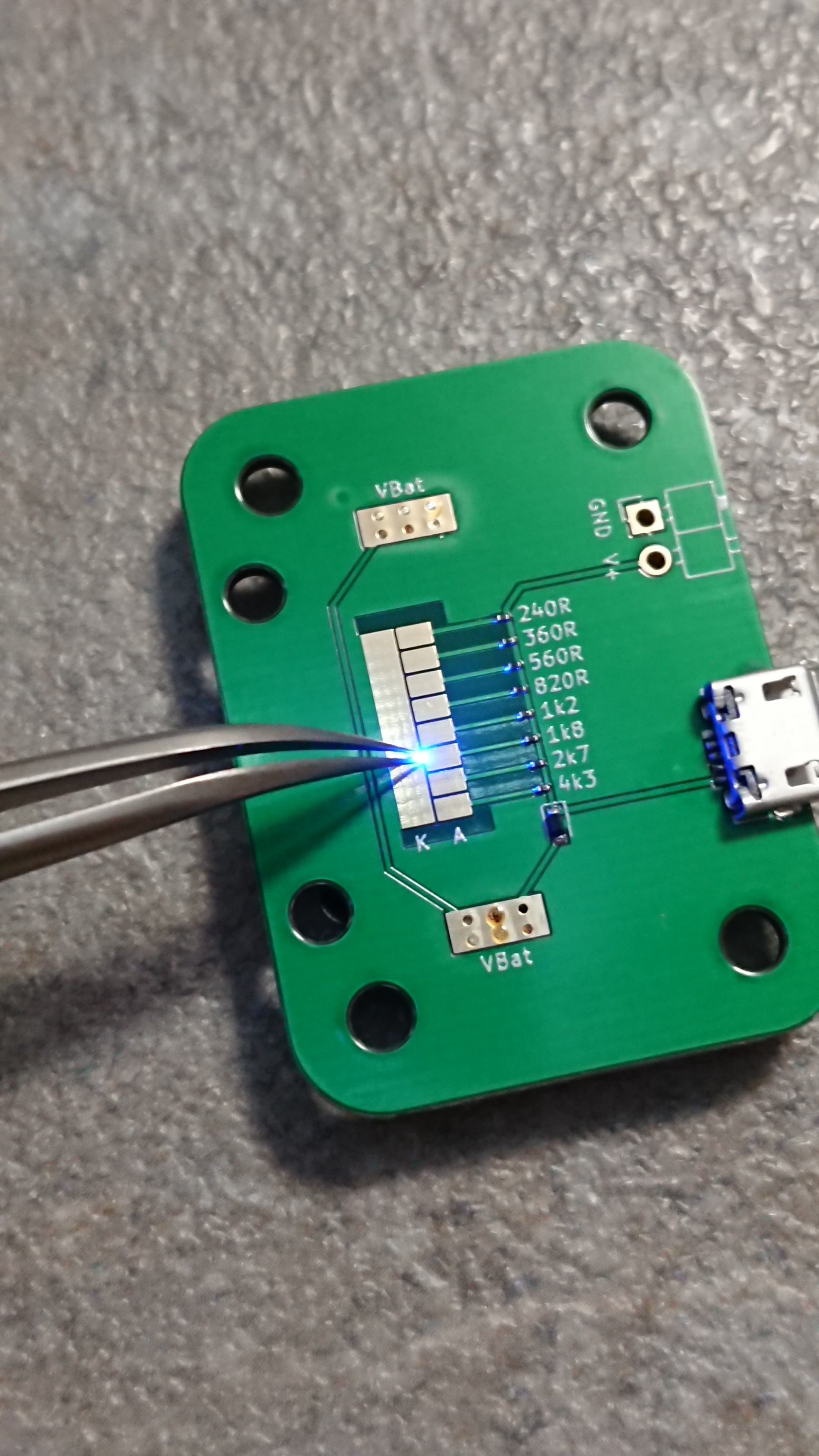
And it works with a coin cell on the bottom and also with USB supply:
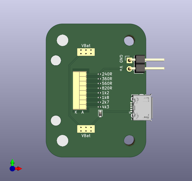
Sorry that this took a year to figure out, but I've finally come up with a design that might not be totally useless, but easy to build and rather inexpensive: An LED tester and polarity finder.
When I had to handle 0201 LEDs, I quickly learned that they don't really come with useful polarity markings. Yes, there's something on the bottom, but when I try to flip them around again even with my best tweezers, chances are that they end up in any orientation. So I need to find polarity while the LED is already facing up.
It's also a bit hard to decide on a current limiting resistor before knowing how an LED will look when a given current is flowing.
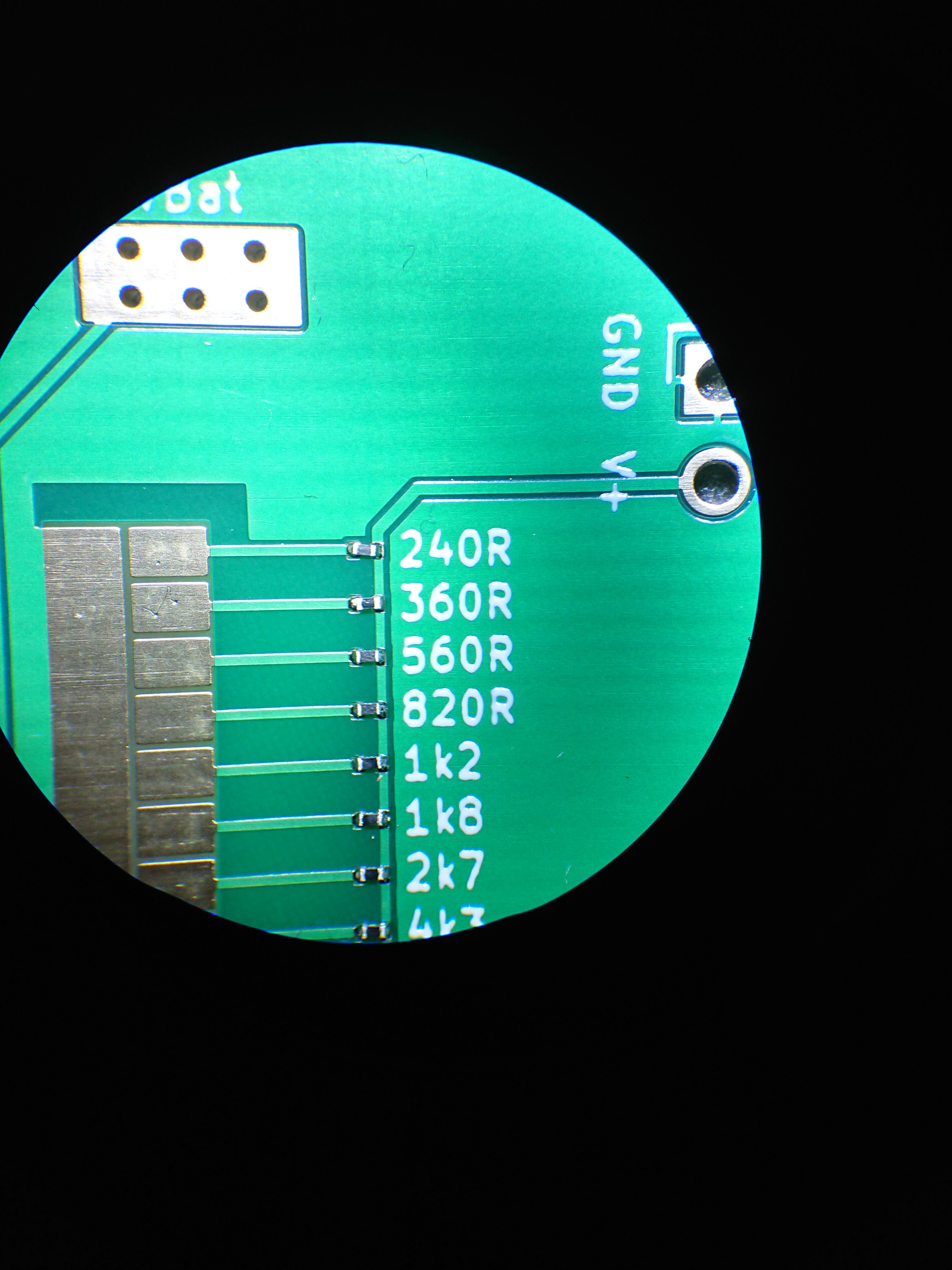
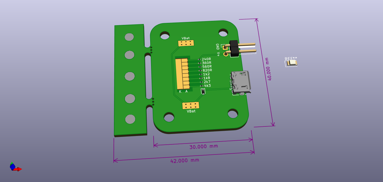
So here's a polarity tester that allows to find the right orientation AND the right current limiting resistor:
Features:
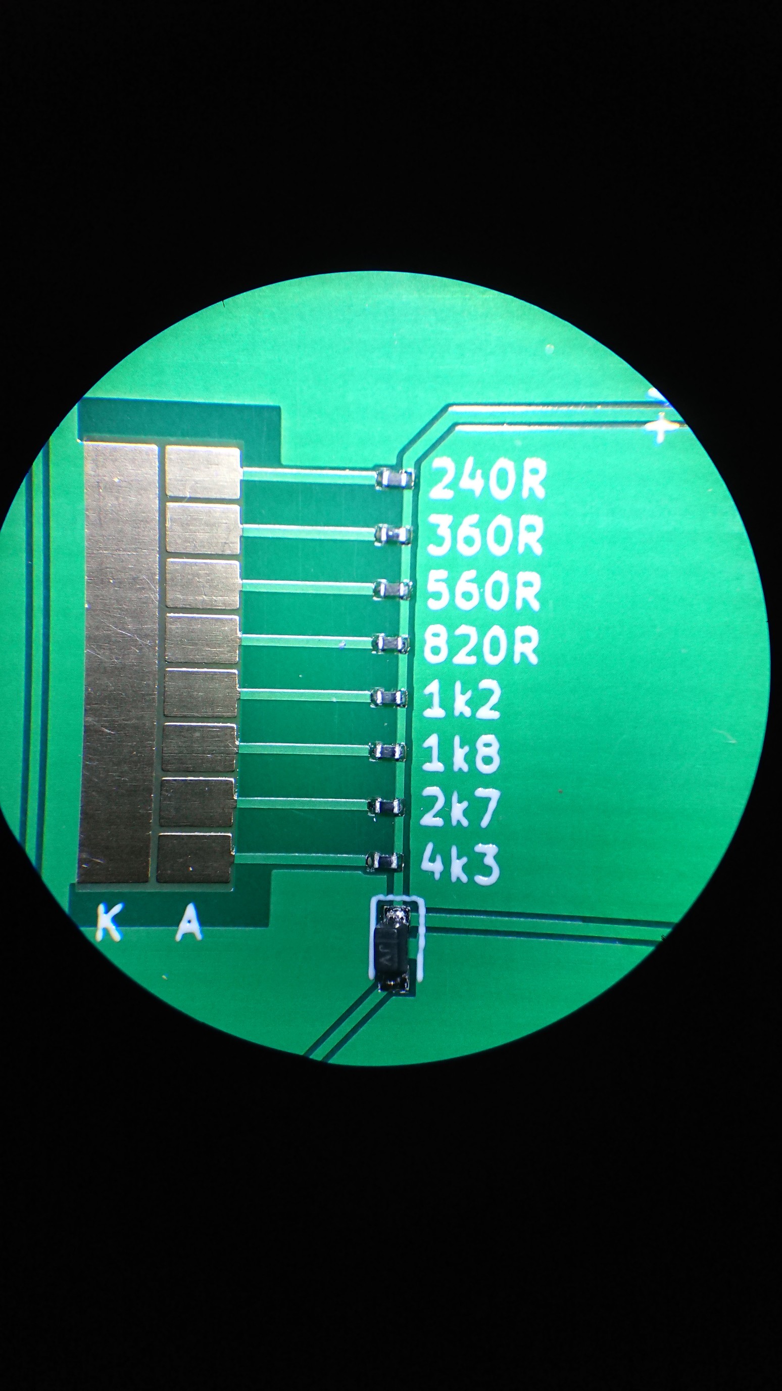
multiple pads to place the LED on, with the large ground pad to the left. The right row of pads is supplied through a set of resistors
resistor values are chosen such that the current even from 2 or 3 pads won't destroy an LED rated for 20 mA
pads are close enough to test packages as small as 0201, but large enough to test up to 1206
supply through pin header (3...5 V), USB (5 V obviously), or a 2032 cell on the bottom through a diode to avoid reverse current when another source (pins or USB) is plugged in
A break-away tab to align the stencil. I'm not going to align this by hand, and a stencil is required to get reproducible results. If I didn't intend to make a lot of these, I'd just pre-tin all pads with a soldering iron.
Usage:
just place an LED somewhere near the highest current limiting resistor (4k3),
rotate until it lights up,
optionally: move to lower value resistors until it's bright enough.
The resistors are in 0201 packages to fulfill the actual purpose of this design: see if the moon phase has an effect on tombstoning. 4 land patterns are stock KiCad, 4 are a custom (hopefully better) land pattern.
 Christoph