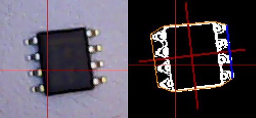
Ok, it's been a while; sorry about this. I haven't update the logs since I fell off the competition, but that does not mean I lost interest to the project, quite the contrary! The project is almost completed. The hardware has been fine for a few months by now. The only function missing from the software is loose parts placement: We all have parts in our parts bins, and the machine should be able to place those too, without complicated trays or jigs. And I already have the optical part routine done:
 Should be simple from here. :-) It would have been nice to get the software fully done before holidays; that almost happened. But right now, I don't have time to even shoot a video, I'll be away with the family soon.
Placement results are not that bad. During development, I use printed images of a PCB instead of real boards. Much cheaper and faster. The downside is that in the pictures below, it looks crappy. Here are some resistors (0603 is 0.8mm x 1.6mm) and SOT-23's. At least some of the placement inaccuracies are because the parts are not always located in the middle of their pockets. But anyway, there would be no problem in reflowing those, so the goal of being able to handle 0603's is met. Hmm, I have to try 0402s... (See below!)
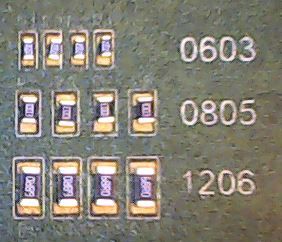
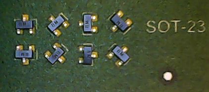
You can see the crappy alignment mark; real boards would likely be even better. The optical calibrations are nice; there are no special requirements in building the machine, the camera and image processing do accurate homing, machine squareness alignment, PCB location, scaling, shear and rotation alignment*, needle wobble compensation, finding parts** and so on.
*: From alignment marks measurements, deriving the transform from CAD coordinates to machine coordinates turned out to be surprisingly hard problem. It sounds like something that anybody who was awake on college math classes could do. But in fact, only the third mathematician I hired for it could actually do it! No kidding, this just one image form an explanatory article he gave me to explain his code:
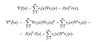
Fortunately the algorithm works, I don't have to debug it! :-) The nice advantage in using an advanced algorithm here is that the PCB doesn't need to be very precise. My laser printer has about 0.2% positive gain error in X and about the same but negative in Y. Doesn't matter. In other words, home made boards will be fine. The PCB placement doesn't need to be accurate either, no special jigs are needed. It is enough that the alignment marks are found roughly where expected.
**: The tape sprocket holes are an easy task for the image processing.
Early next year, I'm going to finish the documentation. I'll post the link to the site when it is presentable. I will show you how to build and use the machine, where to download the software and source code etc. Stay tuned!
Happy holidays!
Update: I couldn't resist, so I did try 0402s:
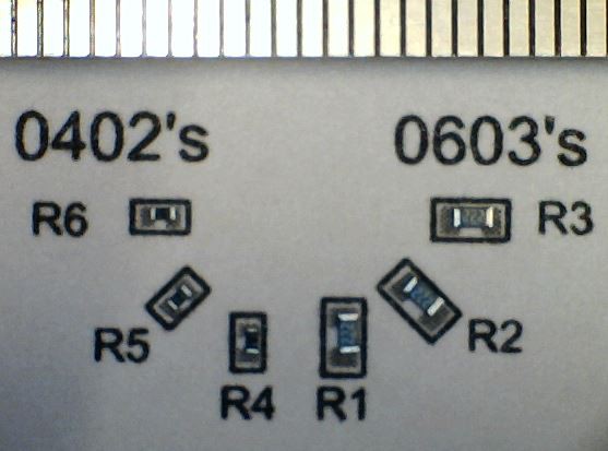
The scale above is mm's; the 0402parts are 1.0 x 0.5mm. Paradoxically, the results are even better with 0402s than with 0603s. That is because with the resistors I have, the 0603 tape has relatively looser pockets than 0402 tape. This is likely vendor specific. Anyway, these would still reflow jjust fine. The conclusion is that my machine can handle at least 0402s easily. I'm happy.
 Juha Kuusama
Discussions
Become a Hackaday.io Member
Create an account to leave a comment. Already have an account? Log In.