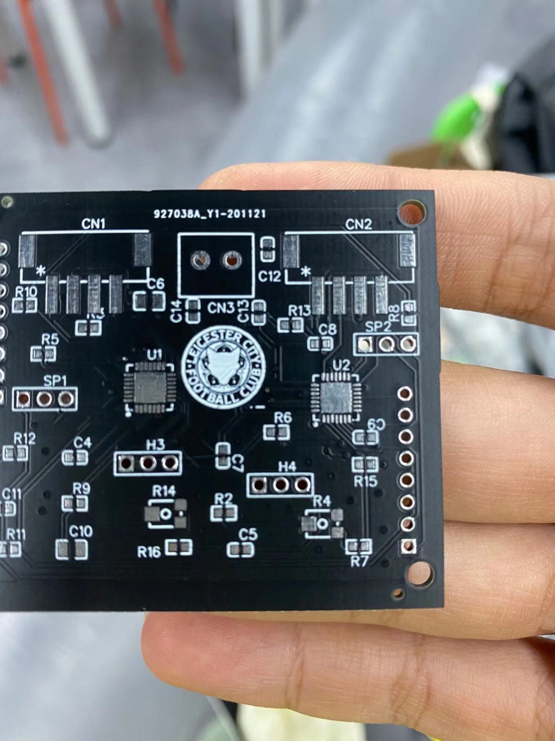
This week, we updated the circuit board (light and motor control board) for our micro-plate reader, it envolved diffrent stages: 1. Design and update components on the previous board( the one we used before) and reroute the electric wire on the whole board. 2. update all the files to lichuang EDA ( BOM fule, pick and place file and Gerber file). 3. Order the board online and wait for EDA to manufacture and produce the board. As shown below, we are measuring the length between two female headers( the outlet).
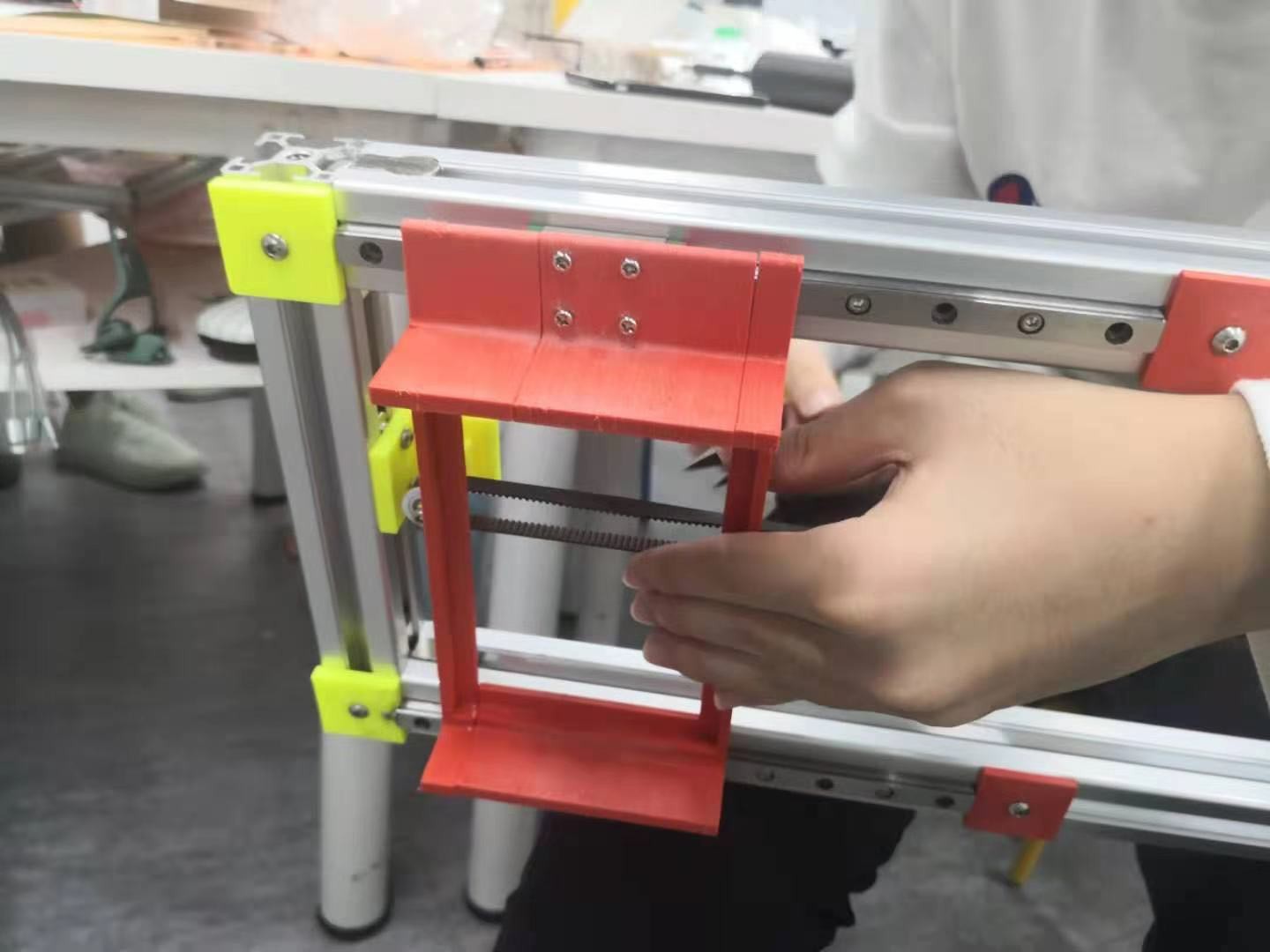
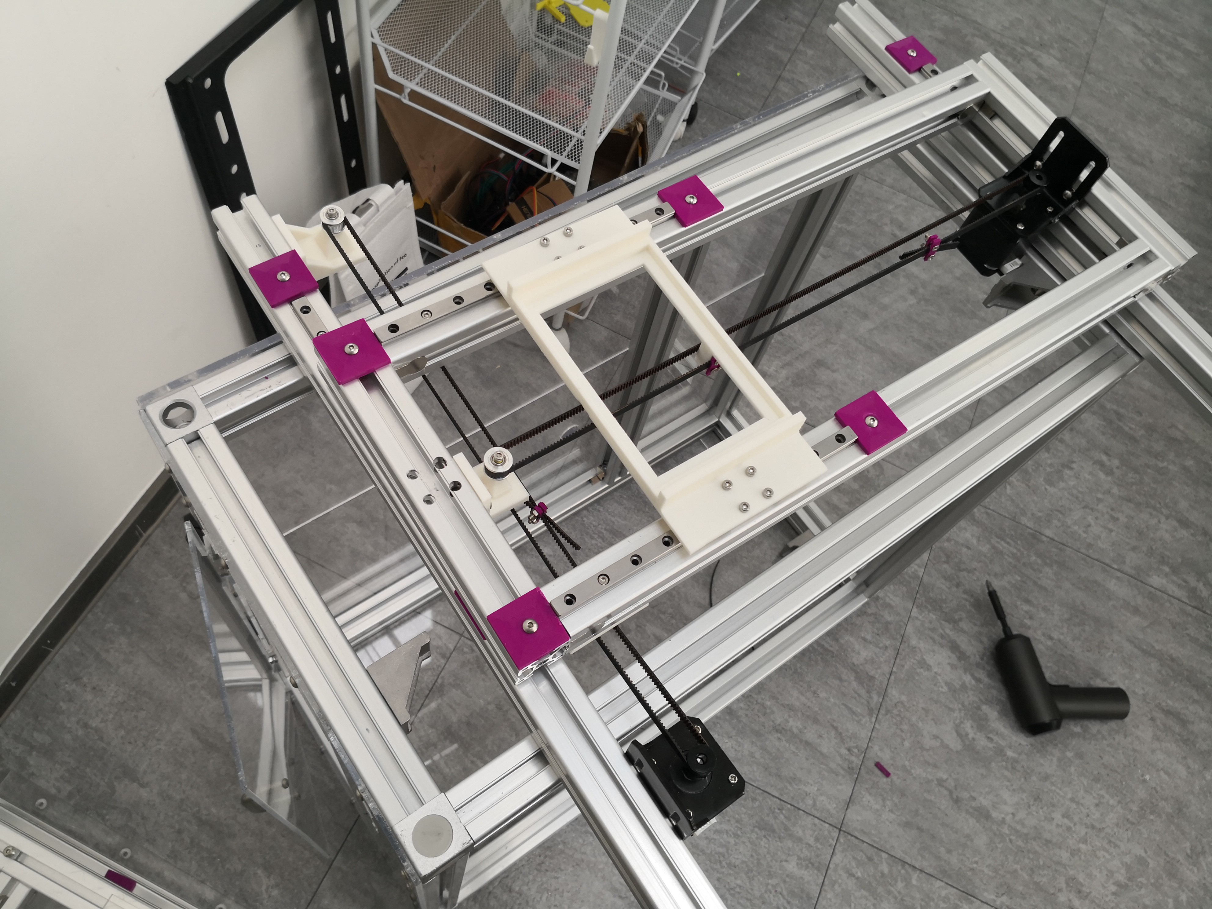
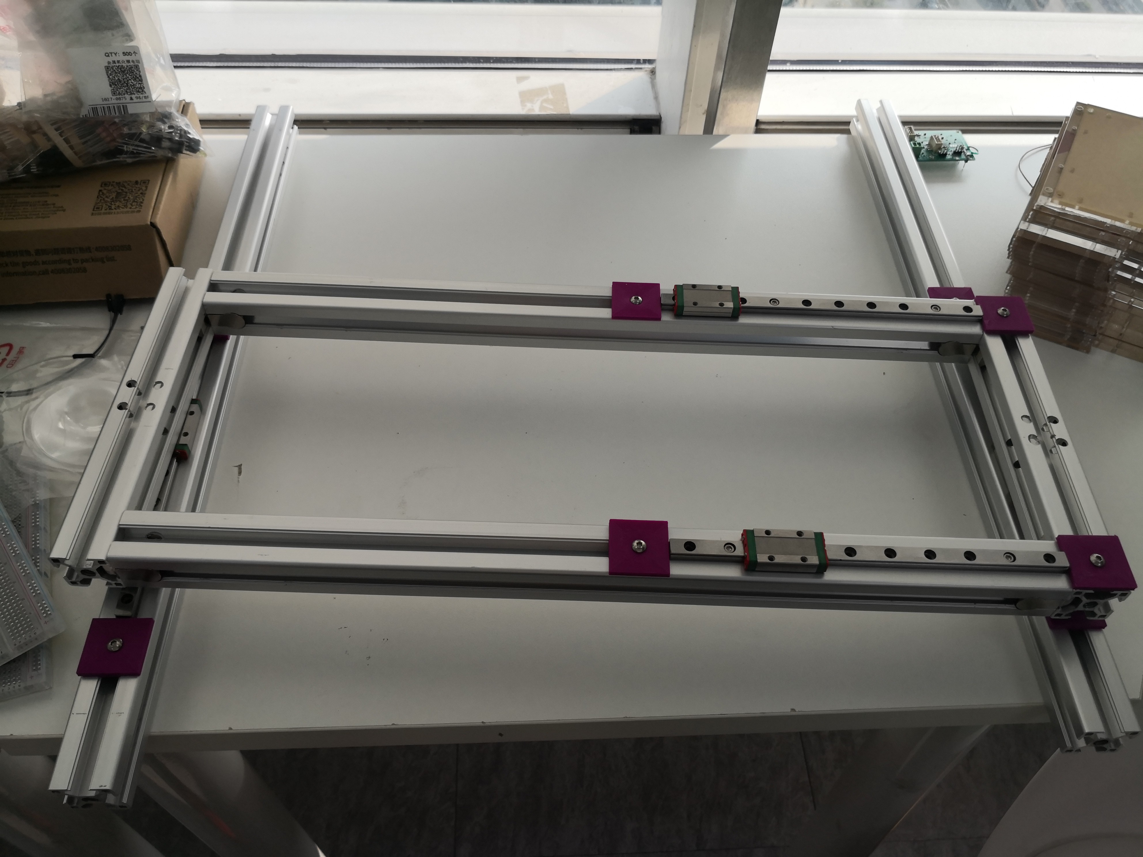
On Day 2 of Week 9, we suffered great loss, our belt receiving gear left us forever, so we decided to remake it with a higher infill rate. And today we finally assembled the X-axis and Y-axis components of the motor, with the belt included and gears needed to receive the belt! Actually a few days ago we already had 3D printed most of the components, however, many of the first draft components broke due to insufficient infill and not careful handling. Therefore, we had to revise the models and reassemble them onto the assembled aluminium beams.
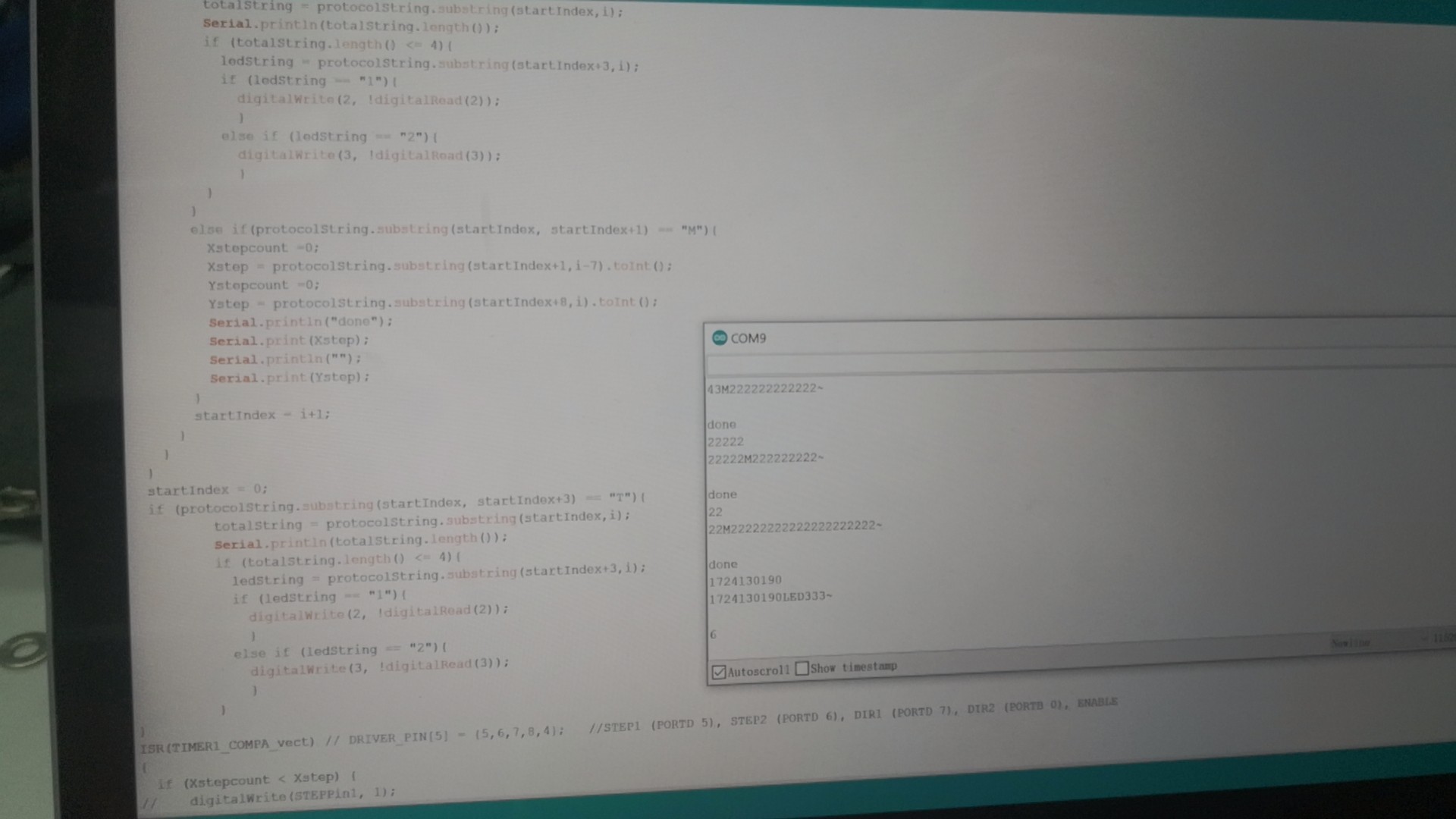
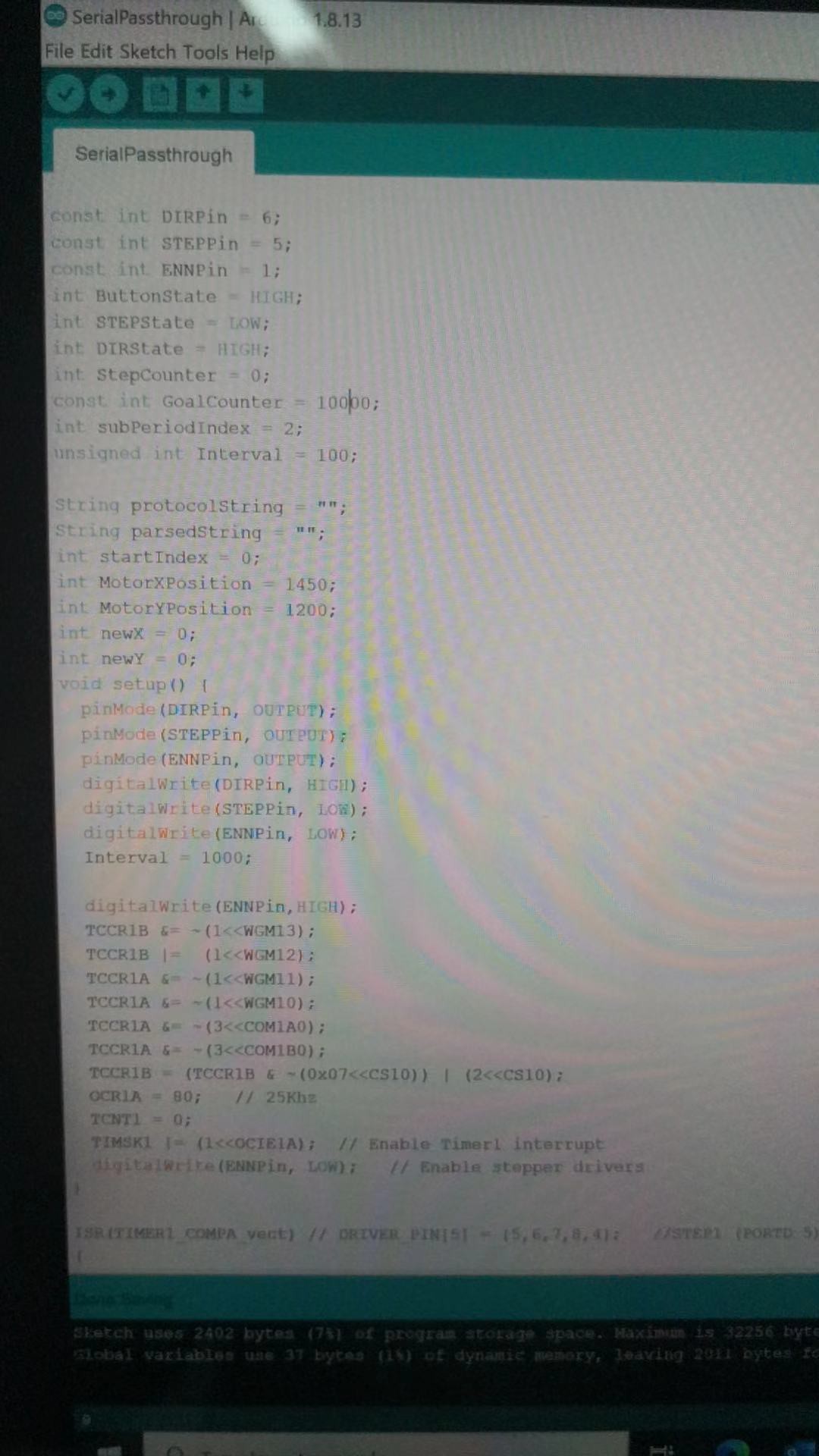
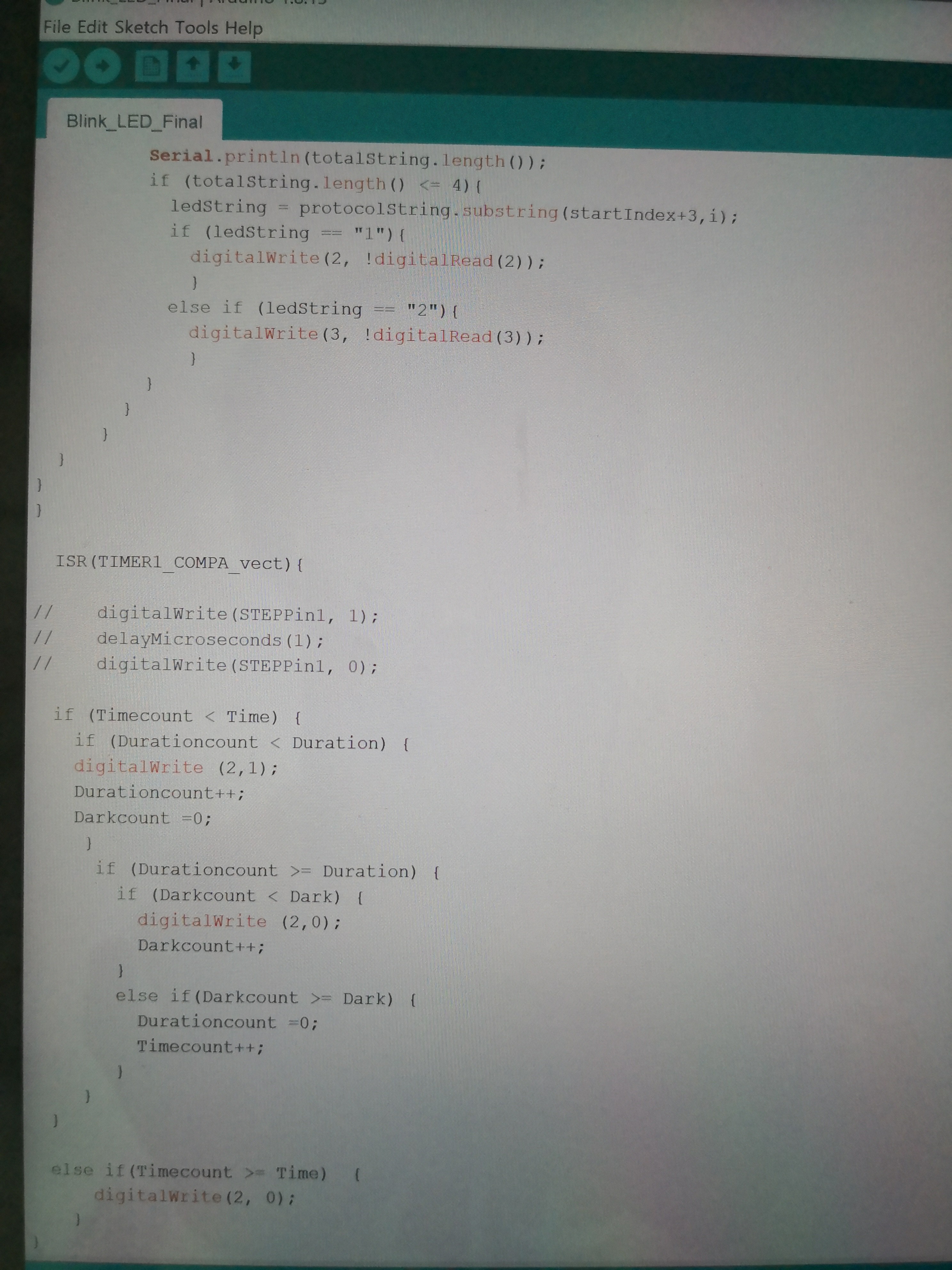
After we finished assembling these components, we then worked on the code to control both motors' movements and directions. Although it took some time, we were finally able to figure out the code suited:
// System Inialization Setup String protocolString = ""; boolean protocolWait = false; String parsedString = ""; int startIndex = 0; String totalString = ""; String ledString = ""; unsigned long Timecount1; unsigned long Durationcount1; unsigned long Time1; unsigned long Duration1; unsigned long Timecount2; unsigned long Durationcount2; unsigned long Time2; unsigned long Duration2; unsigned Direction1; unsigned Direction2; int DIRCount1 = 0; int DIRCount2 = 1; const int DIRPin1 = 2; const int STEPPin1 = 3; const int ENNPin1 = 7; const int DIRPin2 = 6; const int STEPPin2 = 5; int STEPState1 = LOW; int DIRState1 = HIGH; int STEPState2 = LOW; int DIRState2 = HIGH;
void initOutput() { //digitalWrite(ENNpin,HIGH); // Disable motors //We are going to overwrite the Timer1 to use the stepper motors // STEPPER MOTORS INITIALIZATION // TIMER1 CTC MODE TCCR1B &= ~(1<<WGM13); TCCR1B |= (1<<WGM12); TCCR1A &= ~(1<<WGM11); TCCR1A &= ~(1<<WGM10);
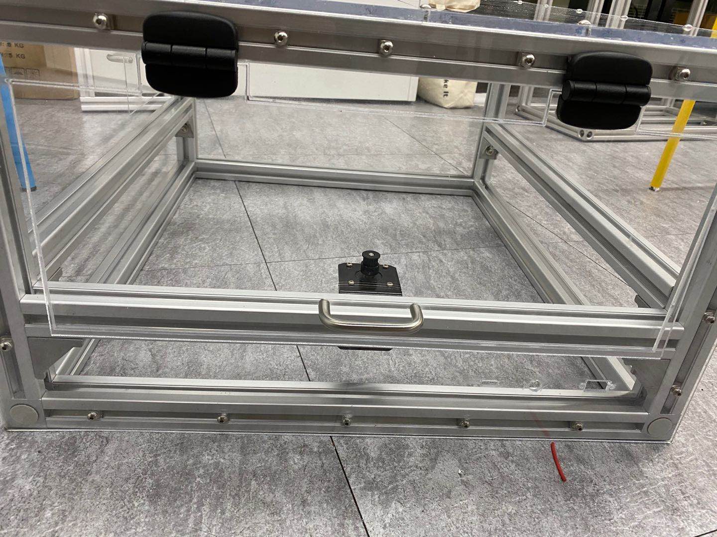
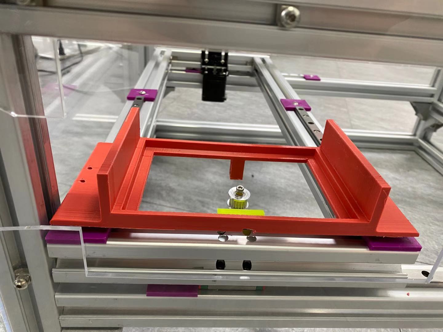
In the morning, we finalized the prototype for the x-y axis of the micro plate reader. Despite it is not the final model that we will be using, the prototype is functioning properly as it moves along the x-axis and y-axis. In the image below, you can see that the micro plate is ready !( somehow).
This is the position where the optical train will operate and illuminate the sample( just to show the idea).
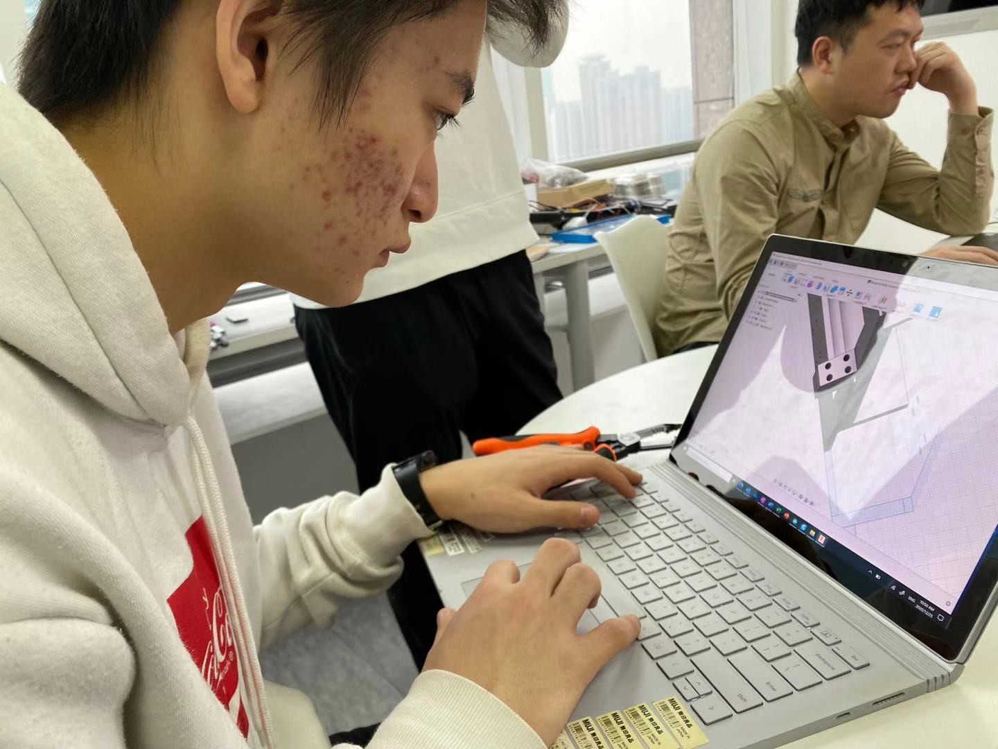
In the afternoon, we learnt the coding part. Our attempt is to expand our knowledge on coding and create a program for the blinking of LED light( we will replace LED light with motor when we master the coding part) However, all of us but warren failed to complete the program. ( warren is drawing the sketch for the prototype !!! featuring warren and Dr. xu).
This week, we will be having four continuous days that we can utilize to continue work on our microplate reader, and because its Christmas Eve today we were all super happy!
As we try try again to write out the code to control the number of times the LED light will blink, the duration of the light to be on, and the duration of the light to be off, one of us finally succeeded in writing out the code in the afternoon! The reason why we tried to write out the code to manipulate a LED light was because the code behind controlling a motor, in which regulates how the plate holder will move in both X and Y directions, is actually quite similar to the code controlling the LED light. The number of times the LED light will blink corresponds to the number of times the motor will move and the duration of each blink corresponds to the movement of each step of the motor's movements.
Adding on, we also assembled the beams, the belt, and the track that regulates how the plate holder will move along the X-axis with those that control the plate holder moving along the Y-axis.
The sense of accomplishment, finally getting things done after weeks of preparation, drilling holes, 3D printing models, and learning how to code, feels just so good as our hears are filled with pride and happiness.
This week, we finalized the hole drilling part for our aluminium beam and constructed them together( as shown below).
This part will become our Y-axis of the micro plate reader. (ps: we are still printing the accessory for immobilization).
In addition, we tried to figure out how to program the advanced code for the microplate reader using Arduino.( we are testing it with the program of LED light. ( here's our progress, featuring Warren's laptop).
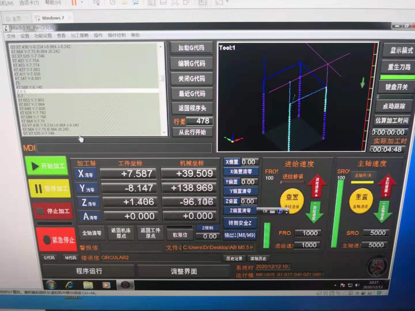
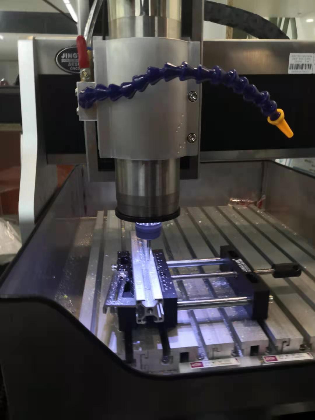
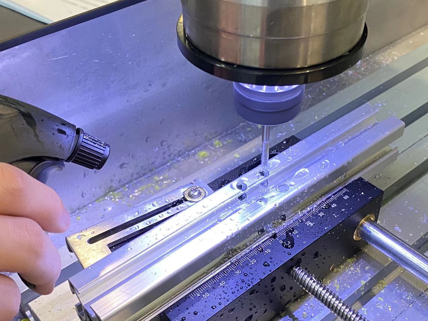
We finish the drilling of the aluminum bars for the x and y-axis of the microplate on the CNC. The milling model uploaded was designed last week. We ran the process without the blade once to make sure no errors were made.
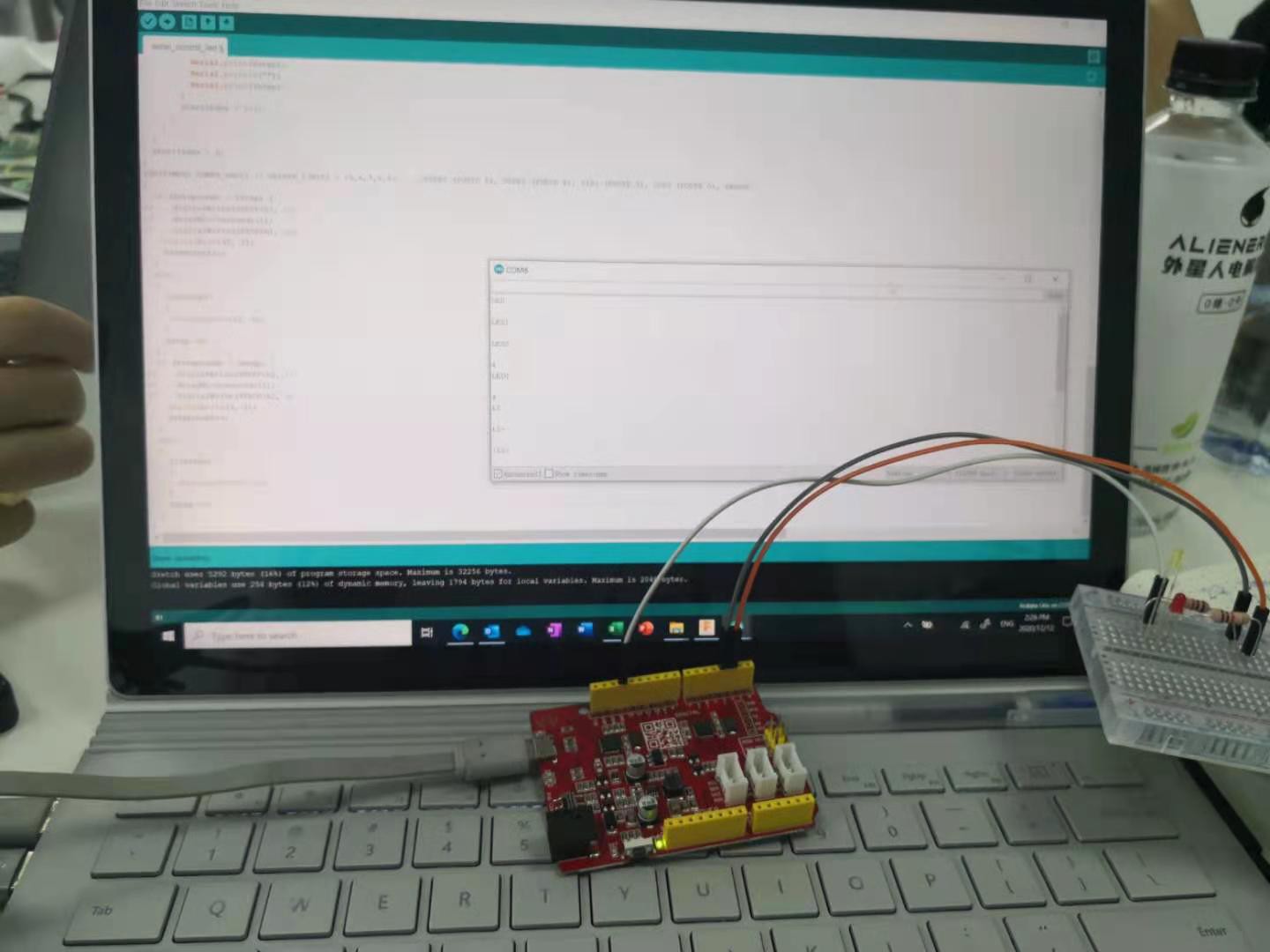
We started to write the program to turn the LED lights on and off on the apparatus. The pin on the Arduino Uno we chose were 2 and 4. We utilized serial transmission to send the command to the Uno. Then, the serial monitor was used to sending commends that were present in the program to the Arduino. The lights are able to be controlled now. Parts of the program were referencing alternating sources.
We were not able to upload and report our progress last week, therefore, we are publishing week 5's log this week. Last week, after we successfully connected the belt, which allows the motor to control the plate holder to move along the X-axis, with the plate holder, we started to devise ways to enable the plate holder to move along the Y-axis. Since we cannot do the same thing with the Y-axis to make the plate holder move sideways because the beams have fixed positions and the only way to make the plate holder move along the Y-axis is to make the whole setup move altogether. Therefore, we begin to plan how are we going to drill the holes on the aluminum beams. We first created a 3D image of the beam via Fusion 360 and then utilized the manufacturing features of it and came up with the pathway of how the holes of the beams shall be drilled by CNC. Unfortunately, the builder we were working in had an interrupted electricity supply and we were not able to use anything, including machines, the wifi, and the plugs, that used electricity, so we went home early:)
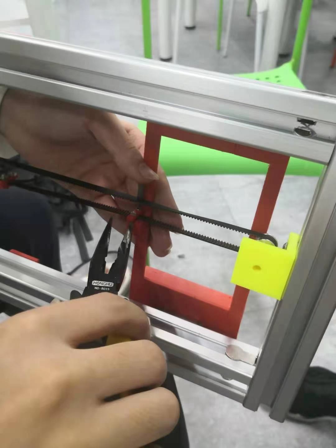
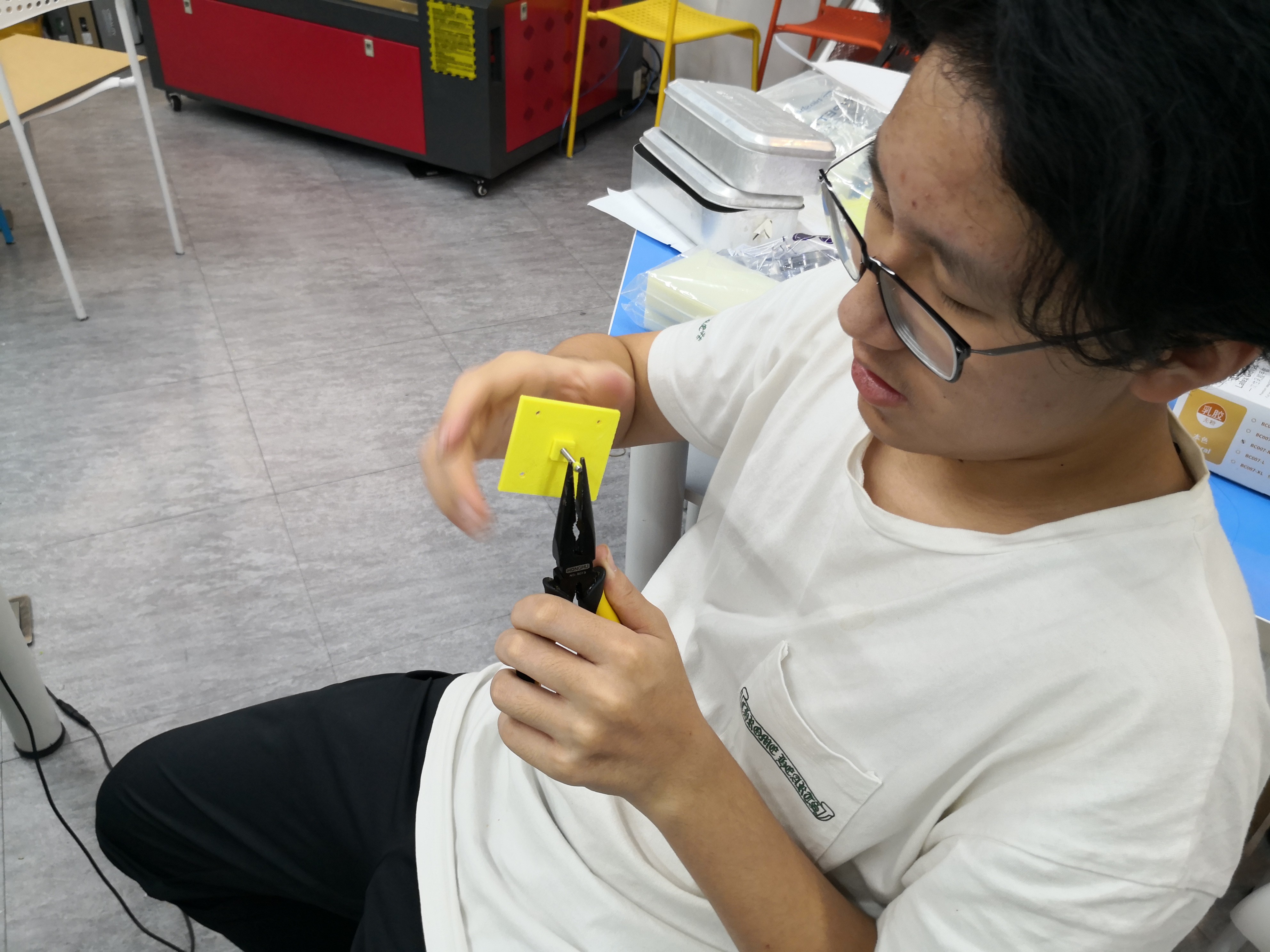
This week, we successfully constructed the X-axis of the detector as part of the main component of the device. Despite the fact that the band track was a bit loose, we were able to adjust it simply using pilers. ( as shown in the image below)
This picture shows the complete model of the sample holder. we designed the model via Fusion 360 and printed it with a 3D printer.
Apart from the actual making of the micro plate reader, we designed the control panel for the micro plate reader( it finally arrived last weekend !) Based on the mistakes and flaws from the last control panel, we updated the data and made a couple of minor changes on the construction of circuit, hopefully it will work this time!
Last but not least, we started with the Arduino programming part. Although it is difficult and hard to scrutinize, I think we we will work this out in the future. ( here is an example of the coding part, featuring warren's laptop).
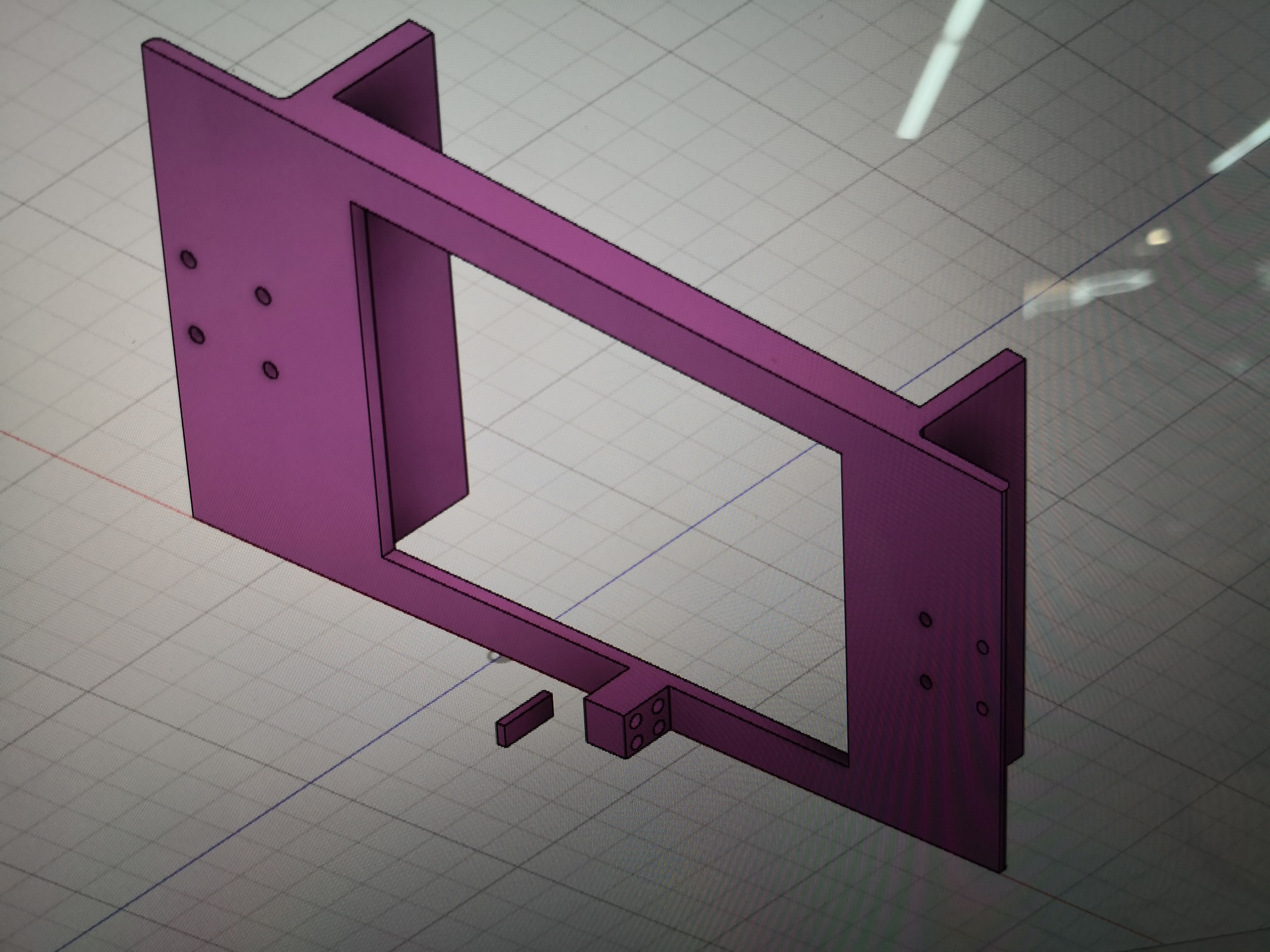
As I'm temporarily separated from the rest of my group-mates, I continued with the laser cutting part of the microplate reader. Today, I finalized the sketch for the right panel holder and its door and cut the right panel with only a few minor issues left.
This image shows the completed right panel and the front panel. The conjunction component provides versatility for the microplate reader as a whole and it enables the door to move in 180 degrees. We also constructed the front side of the microplate reader with the help of another student, as most of the laser cutting parts are done, we will enter the next section of the assembly next week.
As we continue to work on building the outer pieces of the plate reader that needs to be laser cutted. The main focus of the day was that we worked on 3D printing and installing several of the pieces crucial for the motor, the belt, and the plate holder to cooperate better. We had quite a tough time making slight changes to the plate holder,
the holder meant for holding samples in the future, since our plate reader's dimensions and the motors we are using more quite different from the original one. In addition, we also added a piece on top of a motor in order to adjust the height of the motor to make the belt stable and maintain the same elevation throughout. Overall it was quite a successful day as we were able to continue to progress and as we are becoming more and more skilled and confident with the tools we are using.
 liugodric
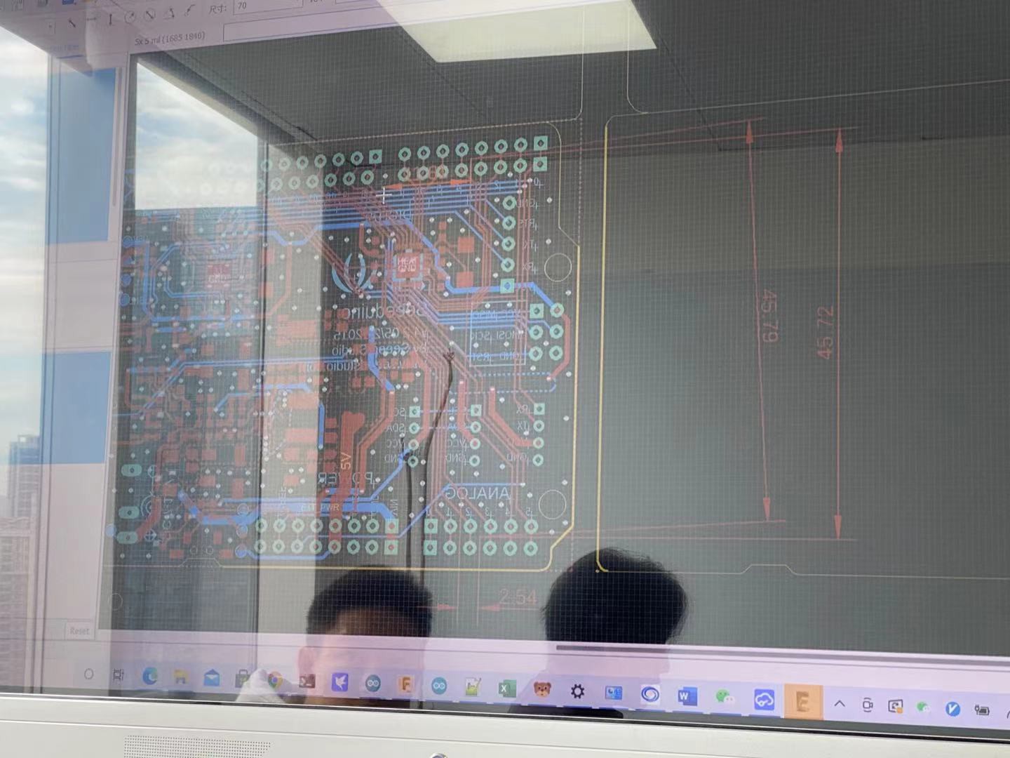


 In addition, we tried to figure out how to program the advanced code for the microplate reader using Arduino.( we are testing it with the program of LED light. ( here's our progress, featuring Warren's laptop).