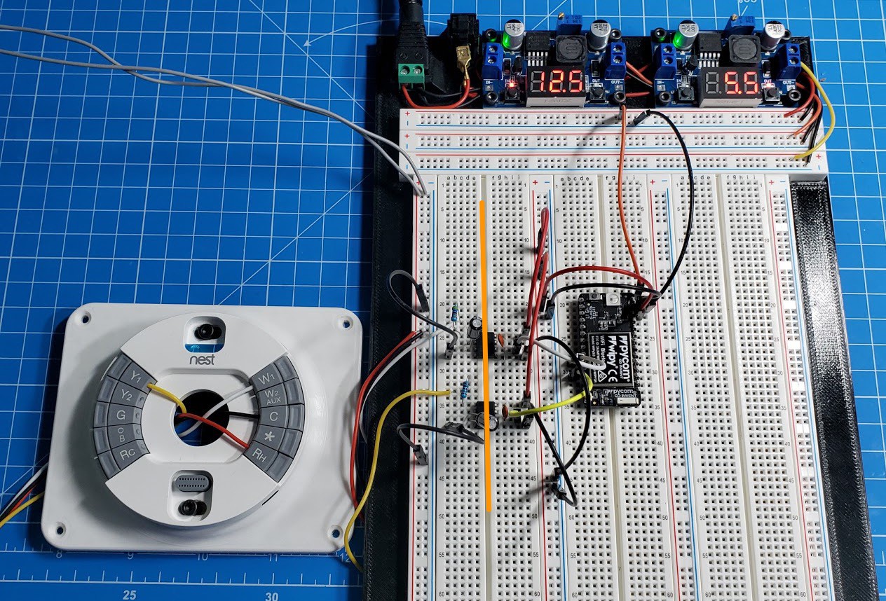
Another 3D printed project prototyping board and a working design that bridged the Nest to the pycom microcontroller.

All AC circuitry to the left of the orange line, isolated from the digital logic to the right.

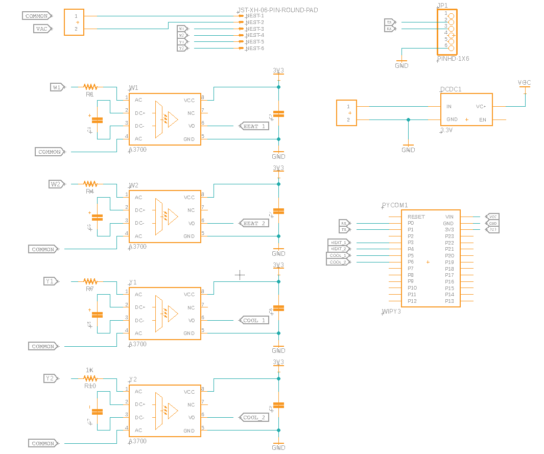
Here's the full schematic which includes two-stage cooling and heating.
I originally had assumed that in order for the Nest to believe it was controlling an actual HVAC system, it would need equivalent 24V AC outputs. Note that the base plate has 10 wire inputs for HVAC connections but the Nest-to-base-plate is a 20-pin connector. As it turns out that to detect what kind of HVAC system that its being used to control, in each HVAC connection is a mechanical switch which determines if there's a wire that's been inserted into the location. Instead of actually running AC HVAC signals, it could be possible to insert wires into the appropriate locations and then leverage the Google Home API to know if the state of the thermostat.
Discussions
Become a Hackaday.io Member
Create an account to leave a comment. Already have an account? Log In.