-
Encoder + Stepper
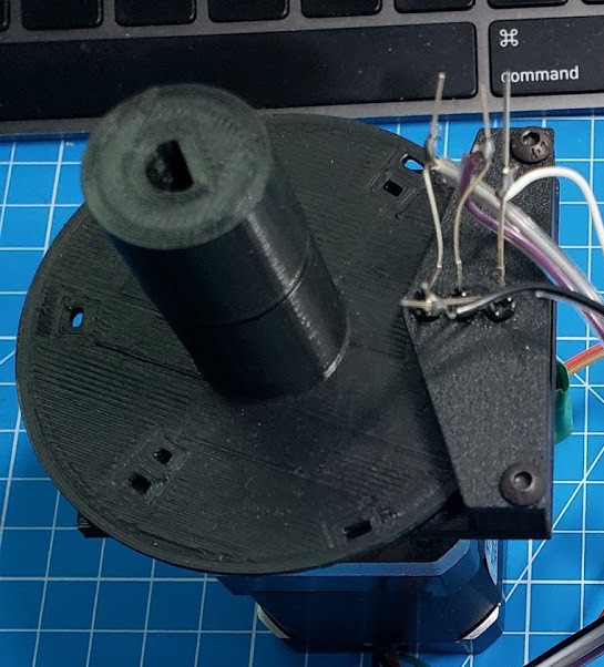
11/09/2020 at 02:50 • 0 commentsNext step: creating a mount to hold the IR LEDs and photodiodes.
![]()
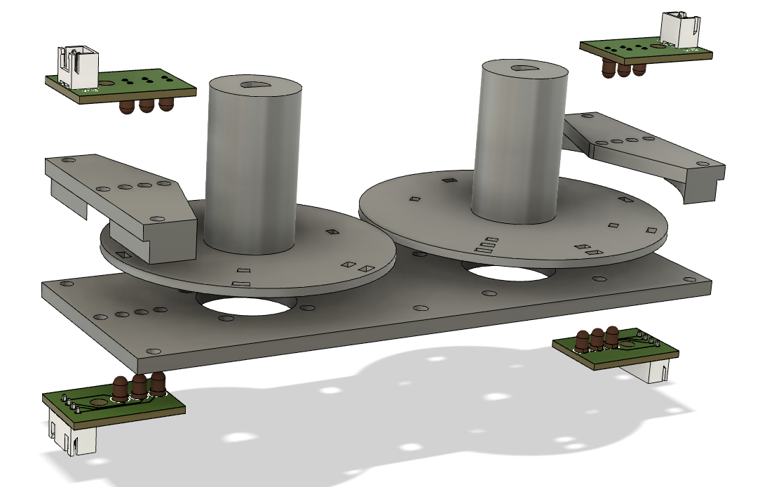
The middle plate attaches to the stepper motors and holds the photodiodes. Once assembled, the encoder disks are friction fitted to the shaft of the stepper motor. Followed by the IR LEDs held opposite the photodiodes on a raised "tab". I had hoped to make this more compact but the LEDs needed to clear the stepper motor housing so the disks ended up being ~2.5" diameter.
![]()
Here is the first working prototype. In lieu of small PCB boards to hold the photodiodes in place, a little CA glue did the trick with a very clumsy soldering of the leads to a flat, multicolored cable that was lying around.
![]()
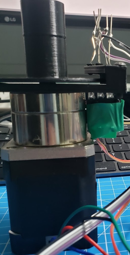
A side view of the prototype. Even more clumsy underside with some electrical tape protecting the LEDs from shorting out against the metal case of the planetary gear casing on the stepper motor.
-
Microcontroller selection
10/30/2020 at 04:48 • 0 commentsI had long been a fan of the Teensy series of arduino compatible boards and have used them in a variety of projects. Reasonable cost and a small form factor with plenty of supported libraries and plenty of I/O pins. But by the time you add bluetooth and/or wifi, one quickly starts approaching the costs of the many ESP-8266 and ESP-32 based chips.
Also, my C programming skills aren't what they used to be. I truly miss the days of the C fluency that I had when I designed UltraSPARC chips for Sun Microsystems. But too much time building web applications in java and python has softened me. And the (re)learning curve of getting back into C is daunting when I'm feeling more like creating something than skill building.
Yes, writing in python yields code that is not nearly as fast. And, yes, it feels like cheating to avoid memory allocation and typed variables on such low-level, embedded hardware. But with clock rates running faster on microcontrollers than the Sparc Workstations I used to develop on, it just doesn't seem necessary to program in C any longer for my use cases.
![]()
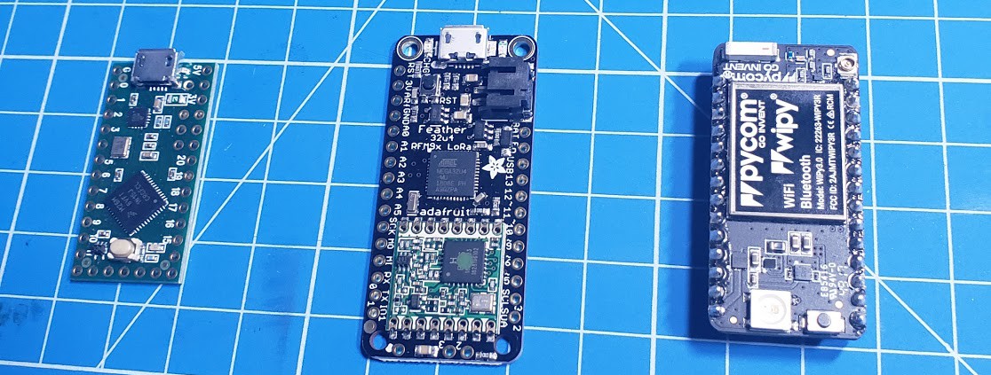
teenyc-lc (left), feather lora (center), pycom wipy (right) Python is more than capable of doing the simple calculations and stepper motion that I need. While I think there is room for micropython to be more "pythonic" (more to come in later posts), the allure of using a higher-level language is too difficult to pass up.
To ease into this new paradigm, I had an Adafruit Circuit Playground lying around after being curious about micropython a year or so ago. I then played around with Adafruit's line of Huzzah Feathers but they can only be powered by either USB or LiPo battery. The stepper motors were going to draw more current than either of those could provide. And the thought of having two DC power supplies for one project seemed silly.
There are certainly plenty of super low-cost ESP32s on ebay and amazon but without a specific company (or a dedicated community) to get help from, I was hesitant to go down that route for my first micropython project. While exploring Adafruit's website, I came across PyCom's line of development boards (and their eco-system and community) seems to be the best of the micropython microcontroller contenders. While their base-level WiPy boards is perfect for this application, it's been good to invest in getting to know a platform that has room for growth since their line includes 3, 4 & 5-network (SigFox, LoRa, WiFi, LTE, BLE) microcontrollers.
-
Absolute encoders
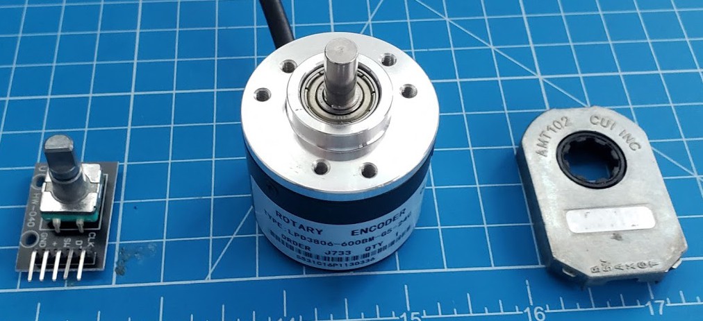
10/29/2020 at 18:00 • 0 commentsI had done quite a bit of research into rotary encoders during a digital read-out project for my vertical mill. The most available (and lower cost) varieties were shaft-based encoders -- either with specific detents (left) or in fairly large packaging (middle) -- are difficult to integrate where two shafts are already connected. The next best alternative is the AMT-102 which, at $20, slips nicely over an existing shaft-to-shaft connection and has remarkable precision (up to 0.08 degrees of accuracy).
![]()
But all of those are incremental encoders and, at best, have a single index point per revolution. Upon startup of the microcontroller, determining where that index position is without hitting the limit of the 270 degree arc couldn't be guaranteed. It could, perhaps, work with the mode selector since you could do a full revolution at startup, but aligning the encoder with the heat-cool mode select knob is not without its challenges.
Options for oiff-the-shelf absolute encoders were even more limited than incremental, most exceeding any sort of reasonable budget ($100+). I did find a reasonably priced magnetic position sensor which had potential, but with only a surface mount package, it was a little out of reach for my limited fabrication tools. Perhaps for the next project.
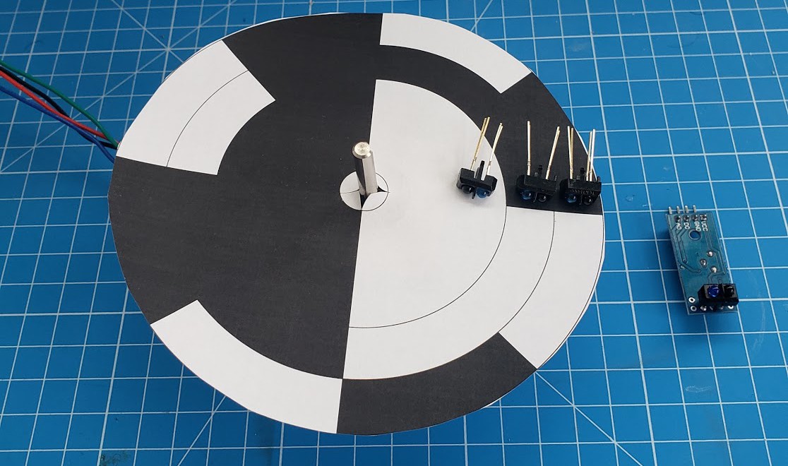
Left with building my own absolute encoders seemed like a possible solution. Typical designs seemed to follow an optical pattern of alternating light-dark pattern with each ring offset by some set of degrees to differentiate the position. With multiple sensors, one positioned at each ring, it creates a binary code for each location: black representing zero, white a one.
Additionally, the infrared sensor (far-right) is ubiquitous in most beginner sensor kits for line following; it contains an IR led / photo-diode pair along with a comparator and variable resistor to tune the IR reflection. Mostly used for line following robot exercises, it worked as a tachometer reflecting off a printed piece of paper for my lathe DRO project quite well.
![]()
Not compact enough for the tight spaced HVAC console, but closer to a solution. My second iteration's attempt was to put the IR led and photo-diode opposite each other with a slotted disc (left) which followed the optical pattern.
![]()
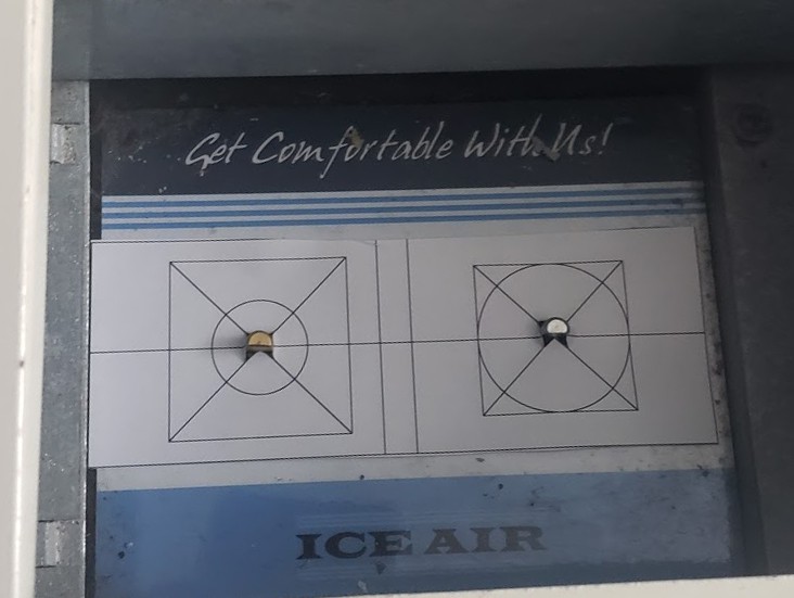
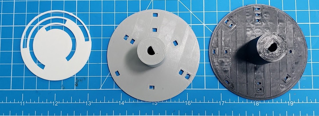
While this provided the necessary number of index points, the resolution meant that the position could be within a 22.5 degree range. For this application, I really needed to know at specific positions and then "don't cares" for the ranges in between.
The next iteration (middle) fixed this problem but with equally sized slots for each ring, as the disk rotated, the inner most slot illuminated its photo-diode before the middle and outer slots. From this picture, you can see that the vertical white line showing up in the lower slot but not in the upper.
Final design (right) created openings that were "pizza" shaped improved the situation, although some software "debouncing" was still required to make sure that the photo-diodes were all being exposed to their respective IR LEDs at the same time. I'll cover in a future post the software for signal debouncing that was still required.
It was also interesting, although perhaps not surprising, that different colors of the PLA were not necessarily opaque to IR wavelengths, hence the change to the darker colors.
-
Turning the knobs
10/29/2020 at 16:52 • 0 commentsThere are two knobs on the control panel. One adjusting the thermostat moves in a 270 degree arc: 135 degrees counterclockwise for heating, 135 degrees clockwise for cooling. The second in a continuous movement at 60 degree indexed positions for off, heat, low cool, high cool, exhaust, vent.
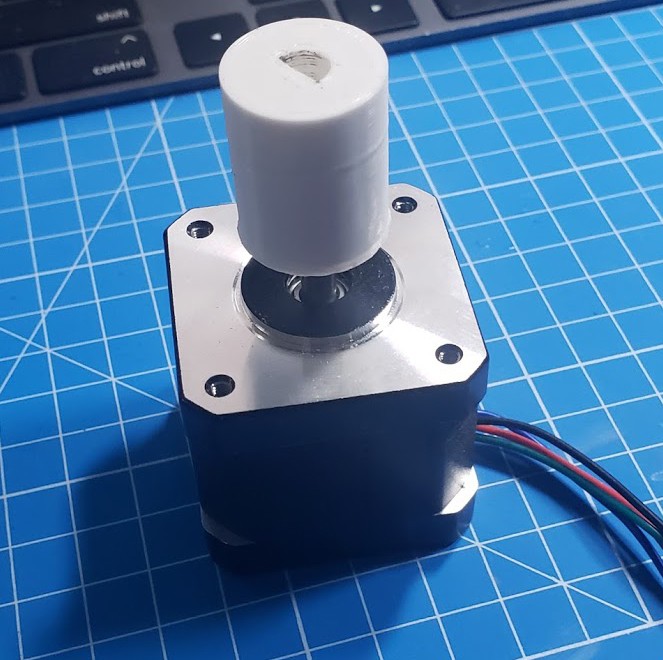
Removing the plastic knob revealed a knob post with a flat, making for a simple, friction fit, 3d-printed.
![]()
Moving the thermostat was easy for the NEMA-17 motor.
![]()
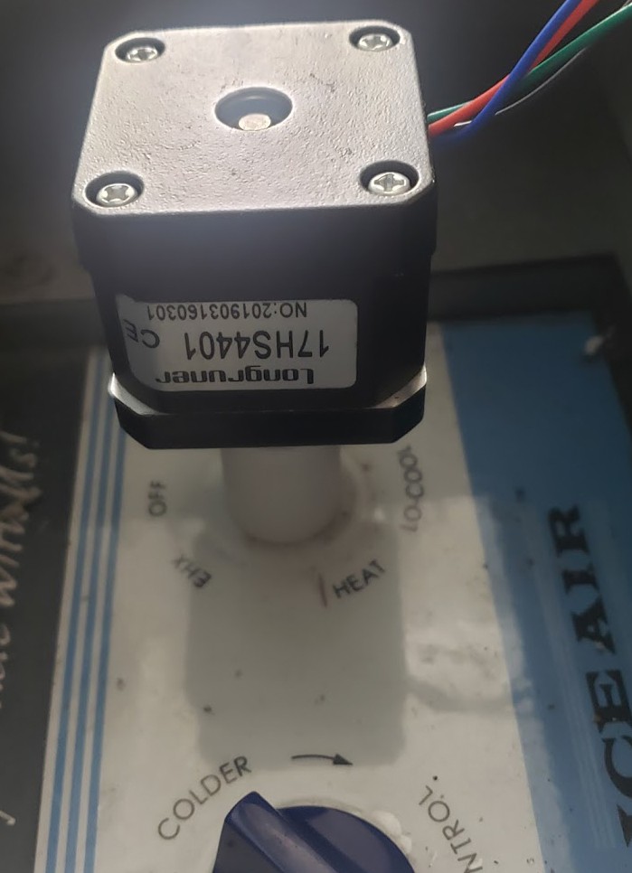
The heat/cool mode selector, however, required more torque than the NEMA-17s that I had could provide directly. I attempted to solve with a more scientific method of measuring the torque but neither the fancy, digital automotive torque wrench or the mechanical one wouldn't measure that low. Elementary school science of a simple spring scale and a foot-long length of material would have been ideal; but would have to wait until Amazon could deliver the $6 scale.
In the meantime, a stepper motor with a 5:1 planetary gear that originally had been destined to upgrade my 3D printer extruder seemed to do the trick.
-
Measuring the physical world
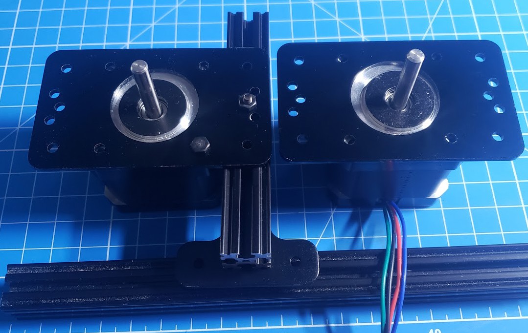
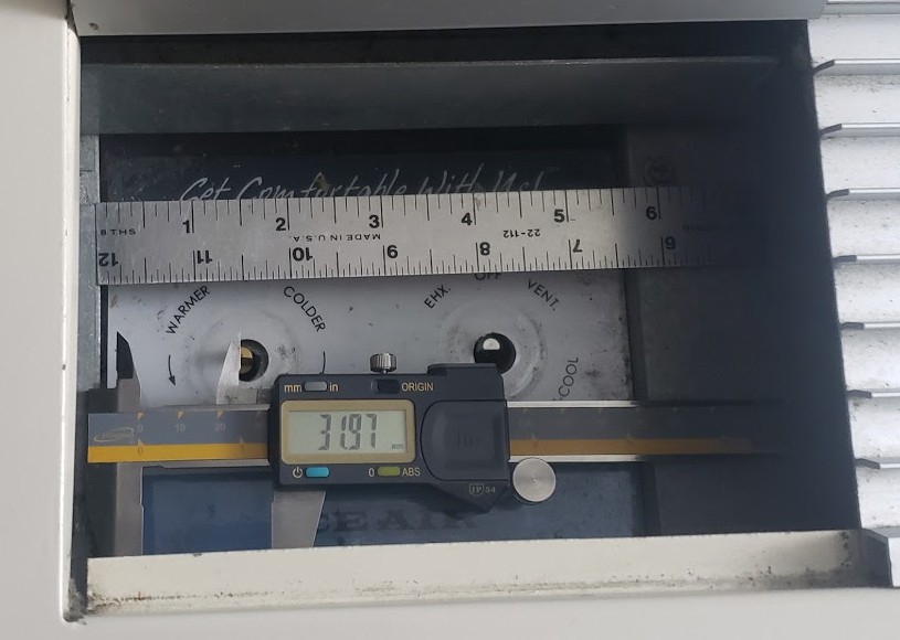
10/27/2020 at 22:46 • 0 commentsKnob control seemed like the best place to start. With a 3d printer (ender 3) at the ready and a variety of random components laying around (stepper motors, drivers, arduinos, etc), task one is to measure the control panel and figure out how to rotate the thermostat and heat-cool control.
The target were the screw in the upper right and position relative to knobs. Not much room to maneuver with the calipers or a ruler. So the first set of measurements were a fail.
![]() Plan B
Plan BUse aluminum extrusion which can be adjusted as needed.
![]()
Not quite enough room in the control panel using these standard stepper motor plates but an approach in a better direction.
![]()
Measure, print and fit to verify dimensions. Nice that engineers like nice round numbers: 2 3/4" between knobs.
-
Analog controls in a digital world
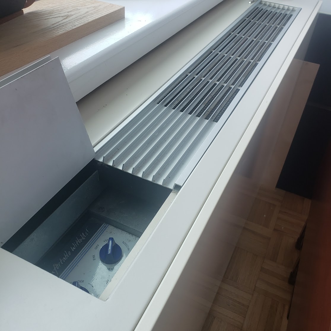
10/27/2020 at 20:01 • 0 commentsCreating one's own space in a new apartment is a fun experience. As is exploring the new surrounding neighborhood of Hudson Yards. By New York standards, the building is brand new; built in 2008. It's spacious (once again, by New York standards) and lots of windows making it bright and sunny even on gray overcast days.
But the heating and cooling system, while energy efficient, is as basic as it gets: heat and cool.
![]()
Beyond the near impossible challenge of keeping the apartment a constant temperature, I found that I missed the convenience of arriving home after work and having the apartment already at the right temperature. Or, worse, finding that I had forgotten to turn off the units before I left for the day and had been wasting energy keeping the apartment cool when I wasn't around.
 Plan B