-
PCB
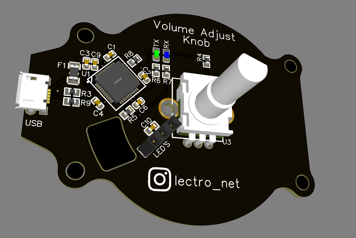
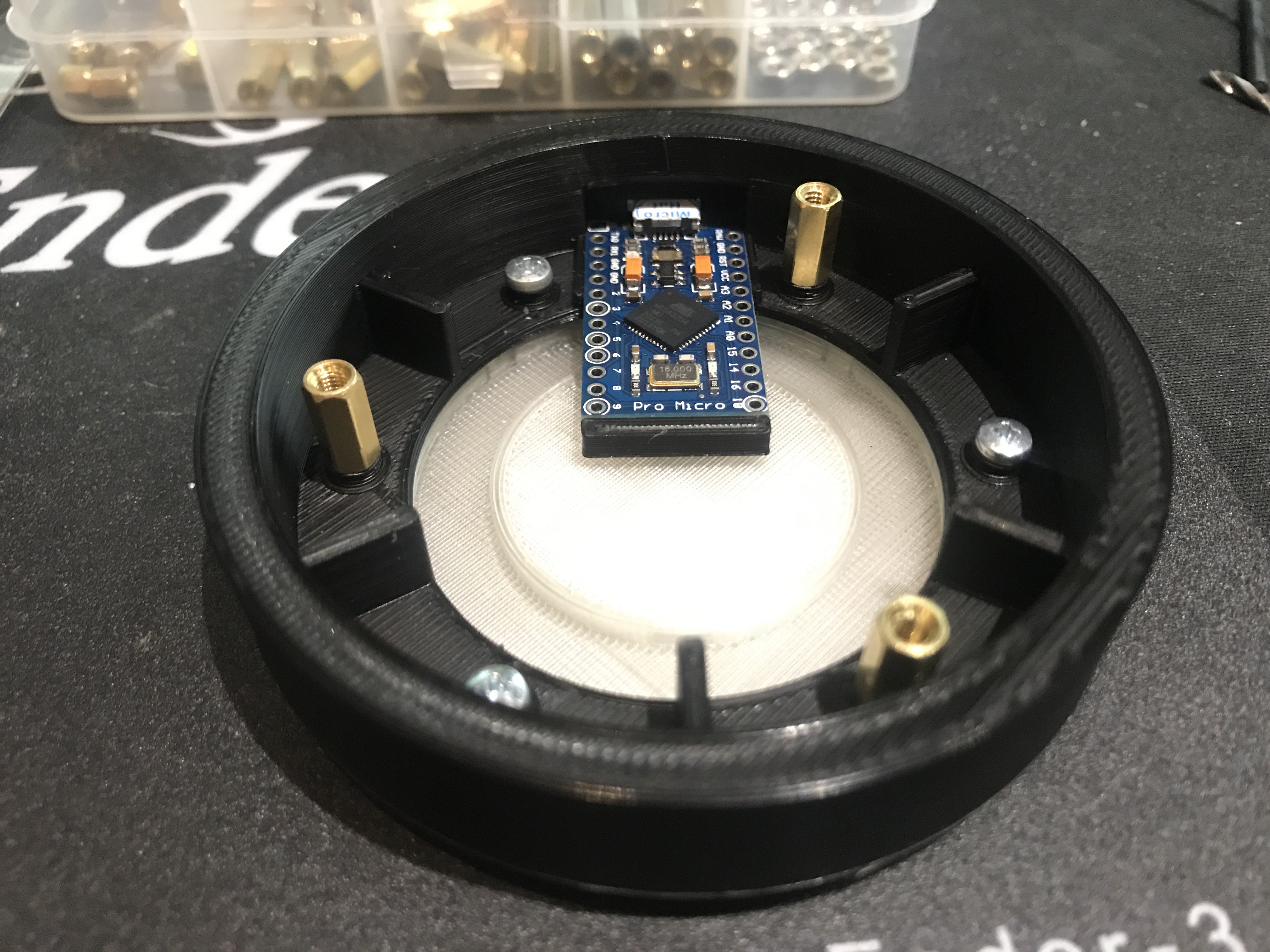
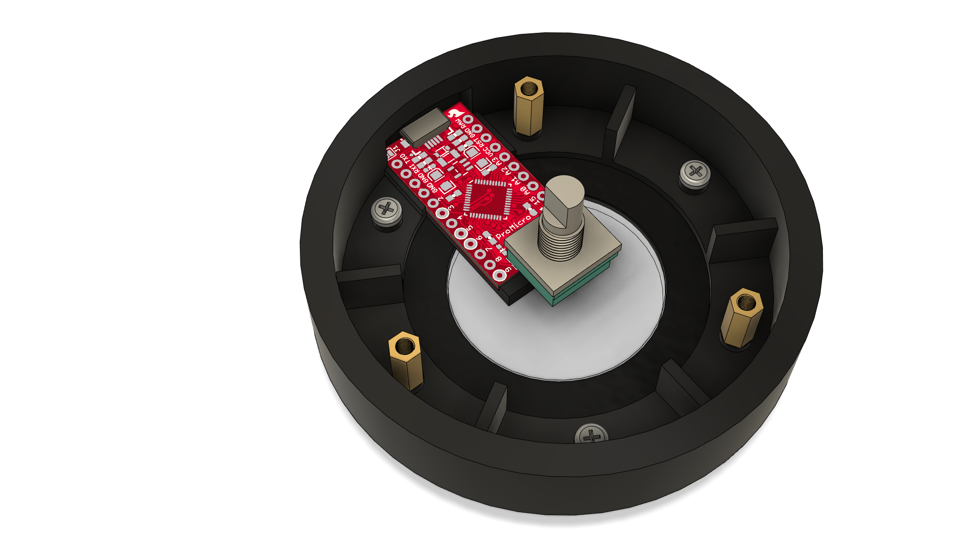
06/19/2021 at 20:54 • 0 commentsI have a PCB designed but still want to improve it so I won't be sending the order in yet but this is more or less how it will look like. I wanted to add USB C but I already have a long micro USB cable I use with my current version so it will just be easier to use micro USB. The space inside the enclosure is quite tight for anything tall like the female header. Some right-angle headers might help so I can easily disconnect the neopixels from the board.
![]()
-
Version 4
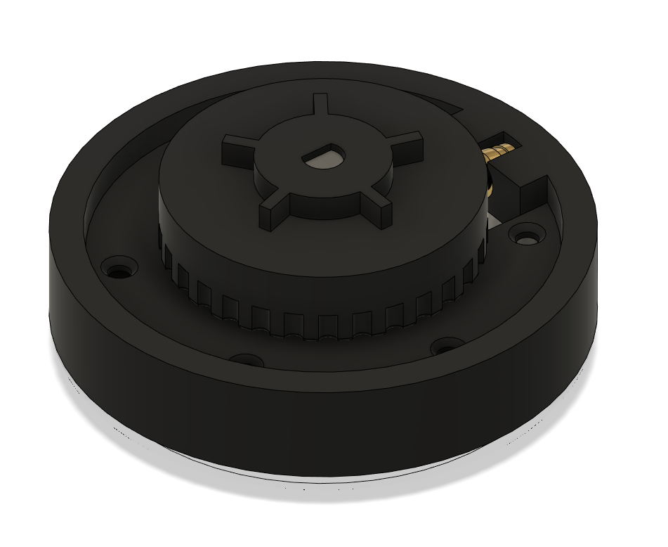
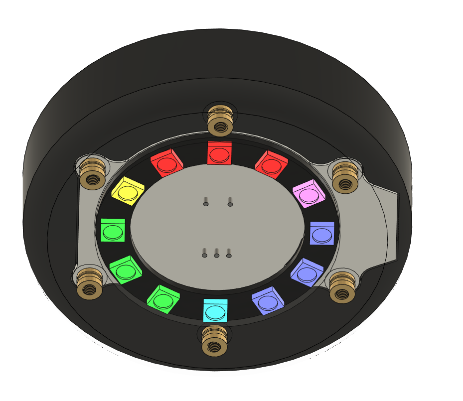
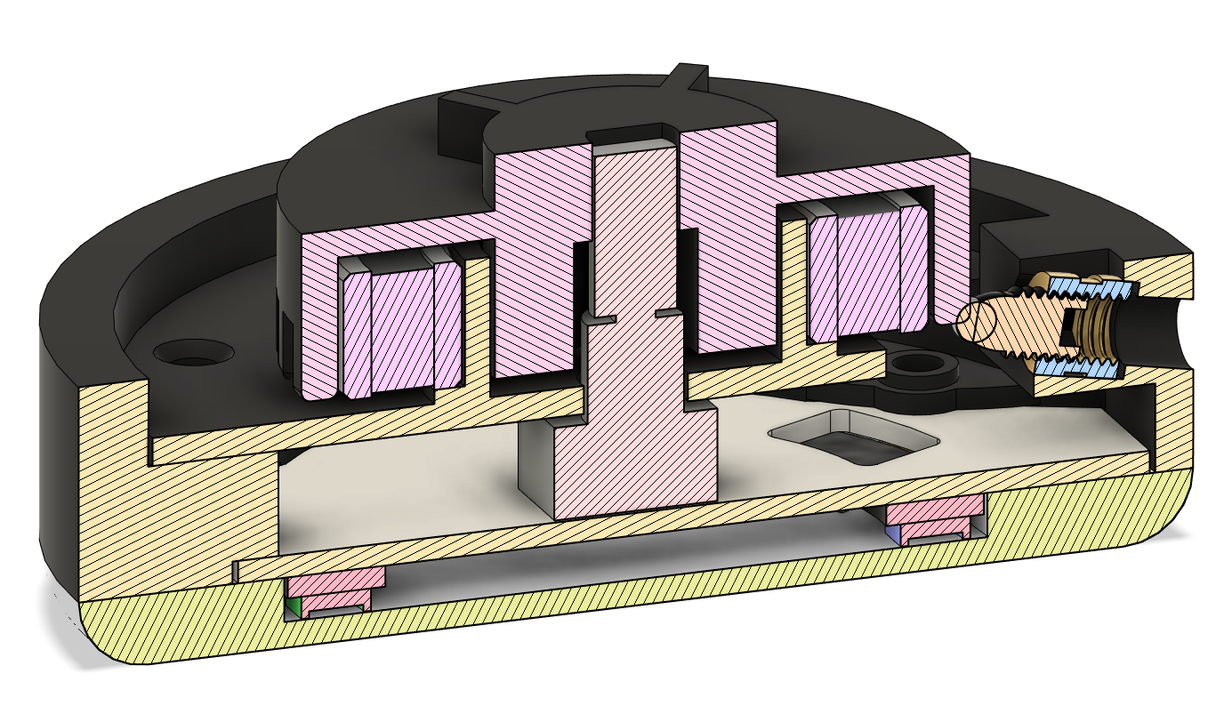
06/17/2021 at 21:31 • 0 commentsI have managed to think of a way to add better indents to the turning action. The PCB is in progress but the housing is nearly complete, currently printing the parts out for their first test.
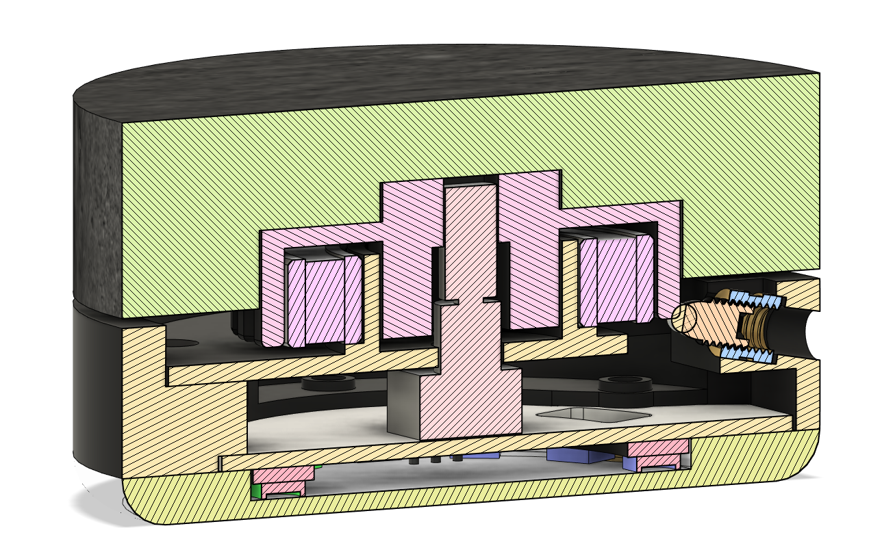
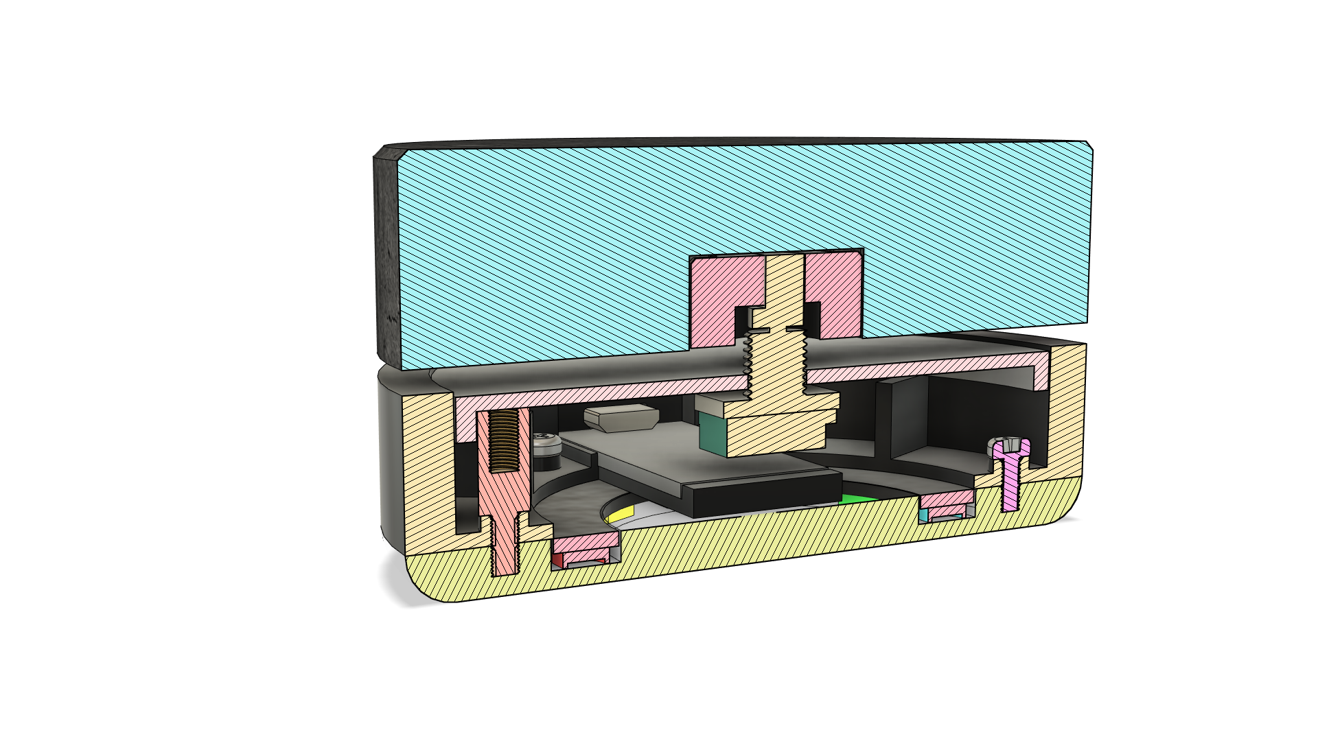
Major changes include:
- Large bearing to help prevent the knob from tilting and to make the turning smoother
- More substantial indent feedback, the force is also adjustable, will not wear down like the built-in one in the encoder (it is weak also)
- Using threaded inserts
- Encoder attached to the PCB itself and the body cover giving two anchor points
You can also see an animation of how the indent mechanism works
![]()
![]()
![]()
![]()
-
Thinking about the next version
04/22/2021 at 21:25 • 0 commentsAfter using the device for all this time, I have found that sometimes my PC doesn't respond to the volume adjustments, after unplugging and plugging the device back in, everything is fine. Happens rarely I think only when I eject my sd card for my 3d printer does it sometimes happen but otherwise, it has been just perfect., easily the best addition to my desk.
The next version will definitely need a strength/stability upgrade and for that, I plan to have a large outer bearing and some kind of additional "indent" mechanism, like a disk with little notches and a metal leaf-spring to *click* into each notch, basically to have a more durable clicking mechanism instead of relying just on the encoder's one as the encoder in my device has lost all clicking feedback. I've been trying to think of a way to get the bearing support but also allow the knob to click up and down, the bearing would have to move with it and therefore the bearing wouldn't be a part of the main body, and so not providing much support. When I figure something out, I will have a custom PCB ready (still learning how to use Eagle though) which will have a pro micro integrated directly onto it but with USB-C. The rotary encoder will also be soldered to the PCB for added strength. I have not had the time to program some additional functions of the RGB ring such as blinking red when the computer is muted or even some device control options, using the knob so for example clicking the knob down and holding for 5 seconds to enter a "settings" mode where I can set a fixed colour or a colour wave.
-
Finished...for now
12/14/2020 at 22:59 • 0 commentsI have managed to finish*, but there's a lot more I'd like to do in the future**, for now, I just have the RGB ring doing an endless RGB wave effect since I don't have the time to figure out how to program other functions but I will surely do it at some point. For now, I am just going to test it out (it's been going well, no sudden volume changes and the RGB ring doesnt freeze.
* I have not made another cement knob, the current one works just fine although the gap between the knob and the enclosure is larger than planned.
**In a future version I plan to find a new encoder although I anticipate it being hard to find one to fit this small form factor but still have a strong "click" when turning. If this is the case I may need to find a way to support the outer side of the knob so when I turn the knob with my finger, the knob doesn't lean to one side slightly (could just make a tighter encoder coupler). I will probably also try to make a PCB just to give myself some practice on designing with the ATMEGA 32u4 and this will also help with the strength of the encoder since it would be mounted directly to the PCB.
For now, expect some silence on this project as I focus on some other pending projects for my workbench which will help me work on more projects easily.
Thanks to everyone who showed their support/interest.
-
Success
11/30/2020 at 18:49 • 0 commentsWas able to assemble the parts together using the screws and pcb standoff's, I will be printing the other parts soon but now I can move onto making a new program for this pro micro.
-
The new model and mould
11/20/2020 at 20:42 • 0 commentsThis is the new model but it is still untested, but after comparing it to the old version I can see that most issues are fixed.
In the full assembly you can see the addition of screws and standoffs. The screws are to hold the middle and translucent section together and the standoffs are to hold the top disk (the one that the encoder screws to) to the middle section. I also found that the knob didn't sit parallel with the middle section, not sure if that is because of the encoder coupler but it seemed like a very good fit, it could be that the coupler itself is not sitting perpendicular inside the knob. I will be making a new knob with a better mould, details are in the next paragraph.
The new mould should hopefully fix a couple issues I have with the current mould.
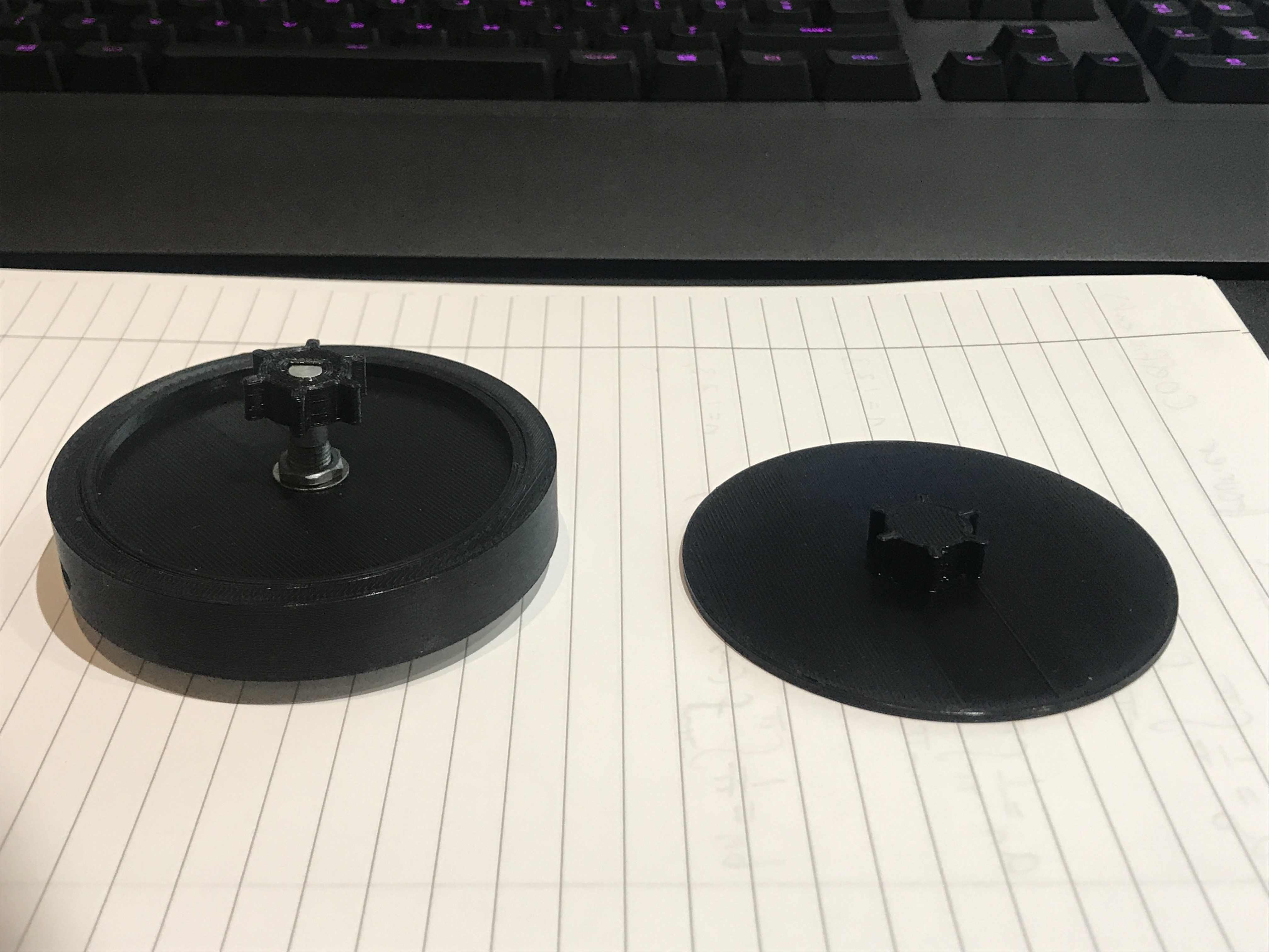
1. Trying to push the top disk onto the cement is difficult because the seal is very tight between the disk and the PVC walls. New version has indents around the circumference in order to let air through.
2. The bottom disk which forms the cavity for the encoder coupler left a cavity which was too tight and made it hard to insert the actual coupler. New version will leave a bigger cavity.
![]()
![]()
![]()
You can see the indents around the top disk here -
Complete revamp
11/20/2020 at 10:31 • 0 commentsI finally gave in and ordered some pro mini's
Currently redesigning some parts after learning from mistakes in my current version.
One big thing I forgot is how I will hold all the parts together so in this version I will be sure to add some screw holes (want to avoid glue).
Will need to make the housing taller since the pro mini now comes into contact with the encoder.
I will publish a more detailed log showing the changes I made when I am finished
-
Mould done but.....
11/17/2020 at 21:19 • 0 commentsI got impatient and proceeded to start moulding the cement, I forgot to drill a small hole in the top disk so the air that was trapped (the seal between the disk's and the PVC sheet was very tight) could not escape and made it hard to push the top disk down into the mould.
Some water was able to leak out from the edges (where the PVC sheet and the bottom disk mate) and this made the knob crumbly around the circumference but it was very slight and ended up looking like a fillet.
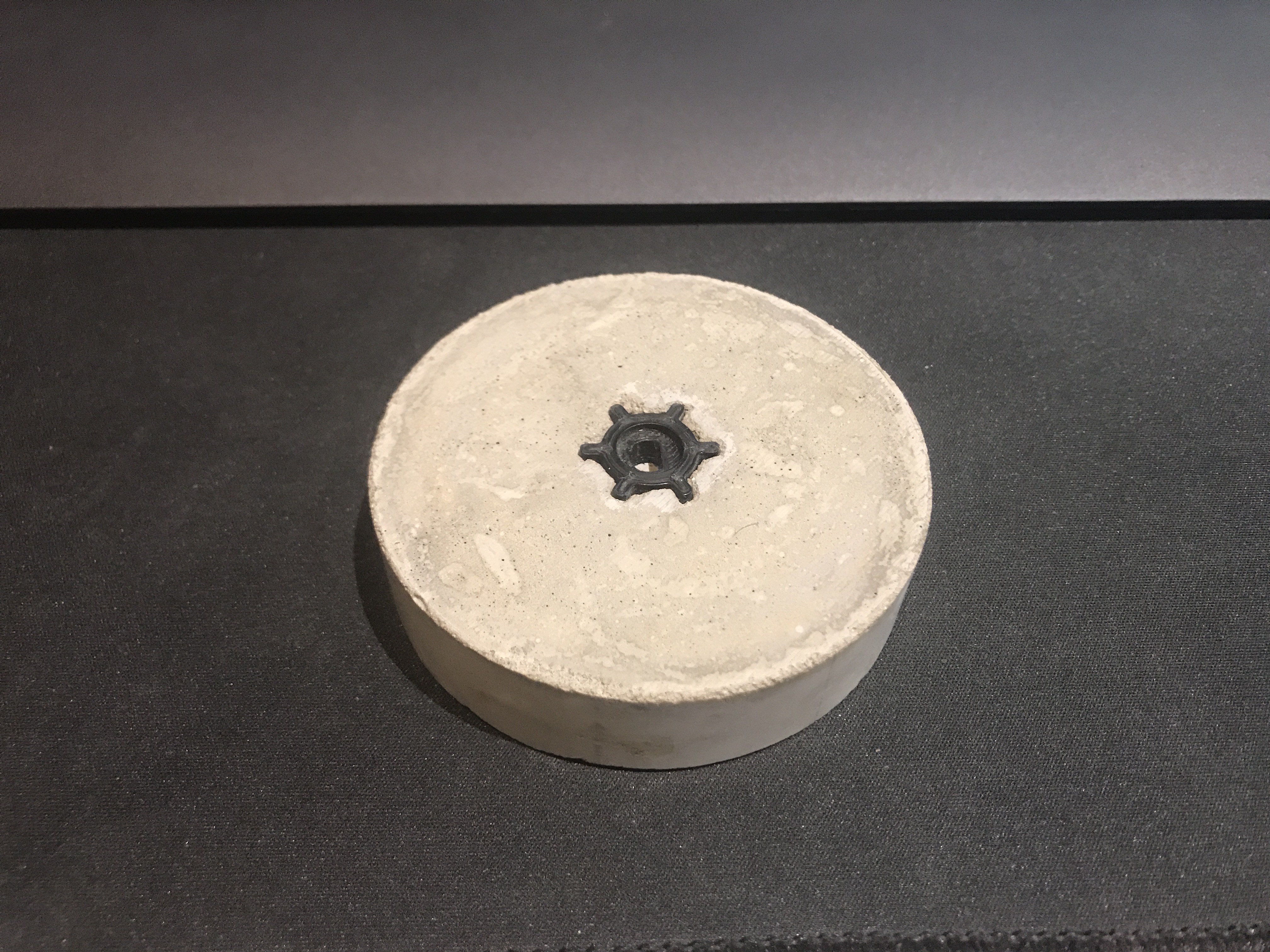
The bottom disk with the encoder coupler blank piece got stuck in the knob and so I had to break the coupler blank away from the bottom disk and then use my hot air rework station to melt the plastic and pull it out. The cavity left by the blank was too tight for the actual coupler to slide in so I should make the blank a little bigger next time.
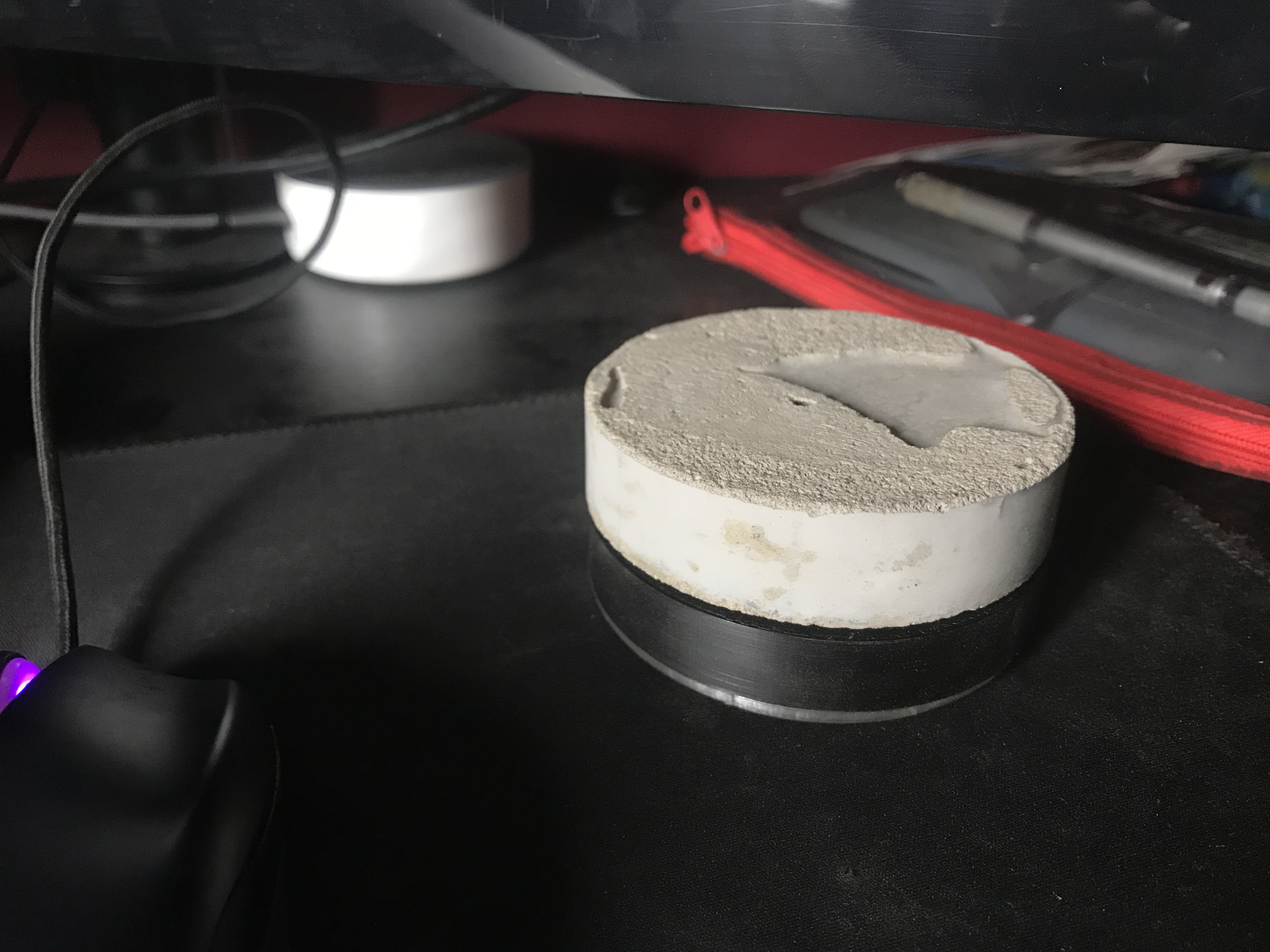
The top surface was ok but had lots of lines (from the bottom surface of the top disk which was 3d printed) so I had to give it a light sanding to remove those and also to level it (ended up also leaving behind a nice textured surface that looks like stone).
I have finally given in and ordered a pro micro, the idea of two attiny85's worked in my head but turns out there isn't enough voltage to power the neopixel ring. At least I will now have the hardware capability to use the neopixel to its full potential (may even add a small button to change colour sequences etc), changing colours when muted or unmuted etc etc. Hopefully will all work out in the end, however I am not sure how I will make the usb port accessible enough for a cable to plug in. I may need to allow for the whole body of the micro usb end to go inside the housing otherwise the corners of the rectangular PCB will protrude out of the housing. I will show an example once I design a new housing.
-
Progress so far
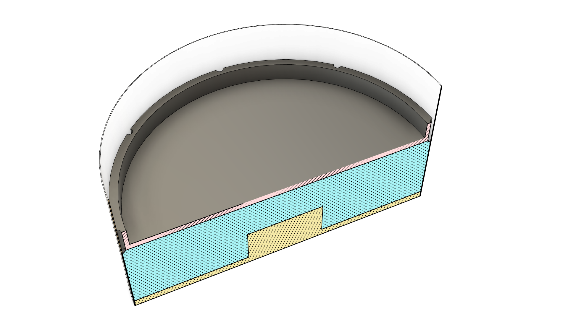
11/15/2020 at 20:10 • 0 commentsMy bag of cement (wrongly called it concrete in past posts, I am not adding sand to it so technically not concrete) is arriving tomorrow so in preparation I have printed the parts that I will need, the encoder coupler (printed twice because it was too loose), the bottom disk with the blank shape of the coupler on it and currently being printed, is the flat top disk and one more part which is an outer ring to fit outside the PVC sheet to sandwich it to the bottom disk to help it hold its shape, and hopefully squeeze the sheet as close to the bottom disk as possible to prevent water leaking out.
-
Re-order the mould
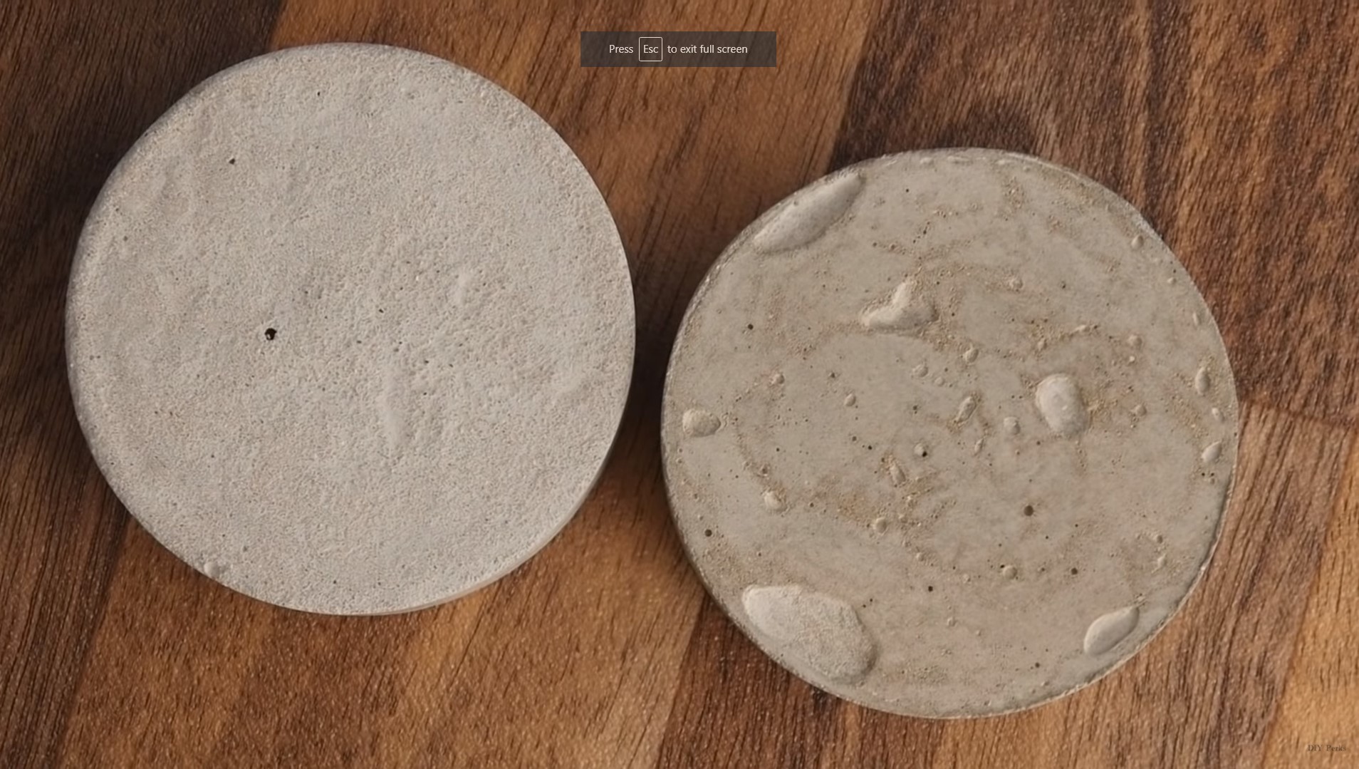
11/14/2020 at 13:42 • 0 commentsI need to flip the mould design upside down, the disk with the encoder coupler should be placed at the bottom, cement poured on top and then the top flat disk placed on top as flat as possible, this is to introduce air bubbles into the top surface which looks a lot more interesting that a smooth or uncovered surface. If you look at the image below you can see the effect of placing a disk on top of the cement and in my opinion it looks way better. I am also considering mixing some black cement dye into the mix in order to produce a black knob which I think will look very interesting. (taken from DIYPerks youtube video which originally gave me the inspiration for this project).
![]()
