 Nikola Secerovski
This item on the arcade check list i long-overdue, all the components have arrived weeks ago, but i was to lazy to do this task. These are the components I put together:
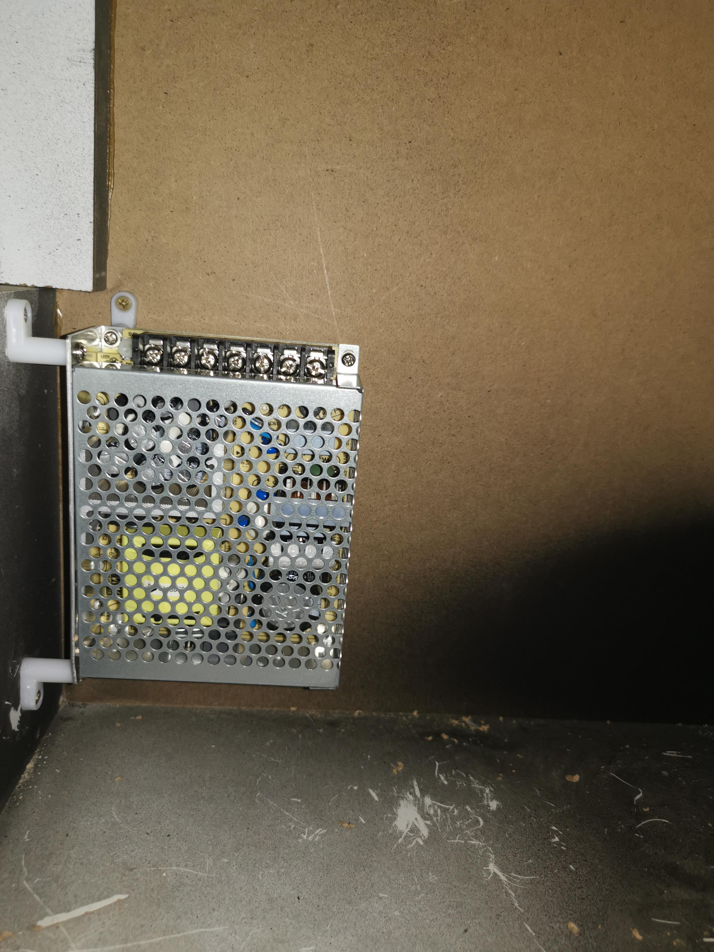
- Power supply (Dual rail, 5V + 12V, SMPS)
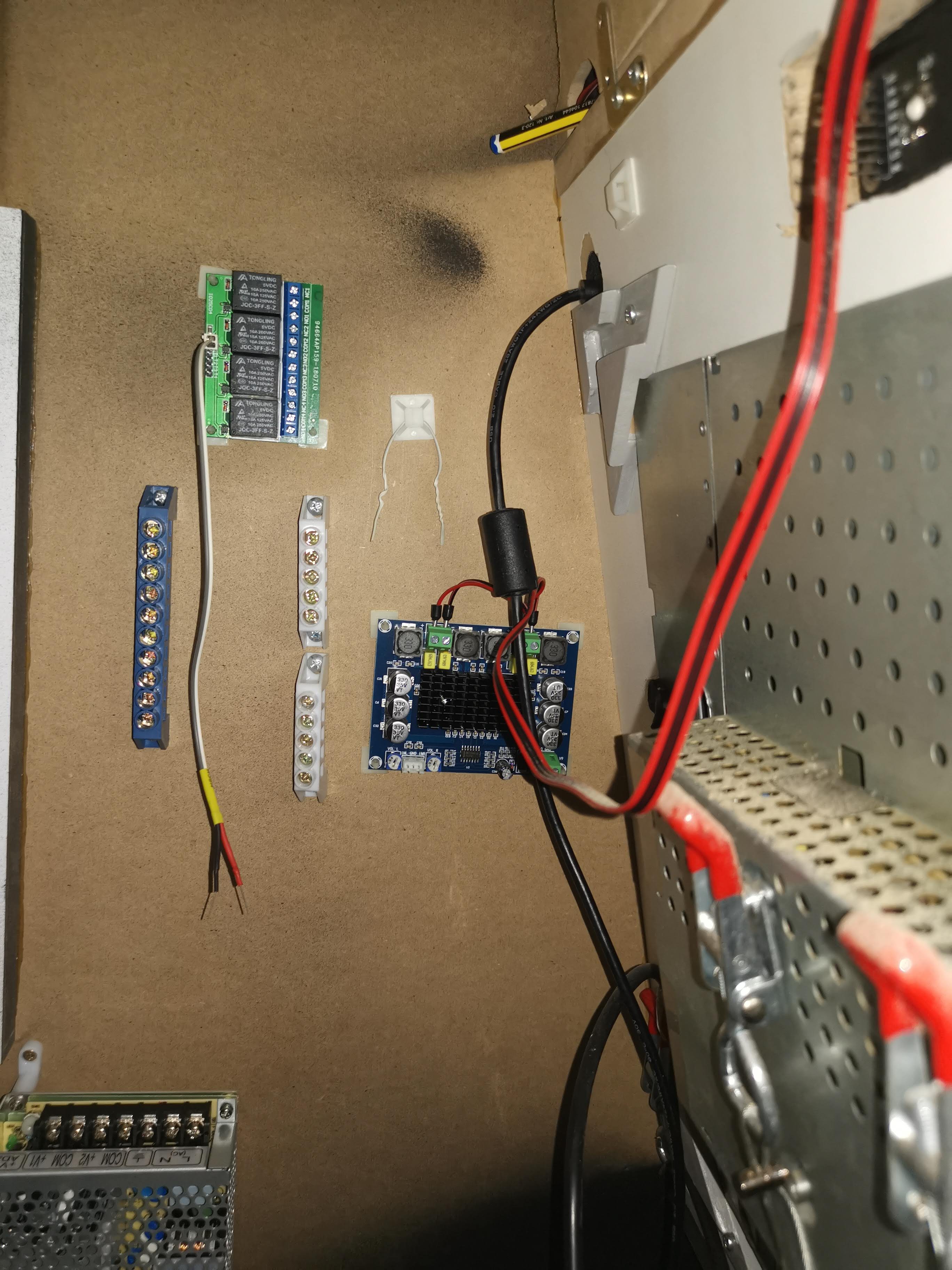
- Latching relay module board (4ch)
- Audio amplifier (D-Class)
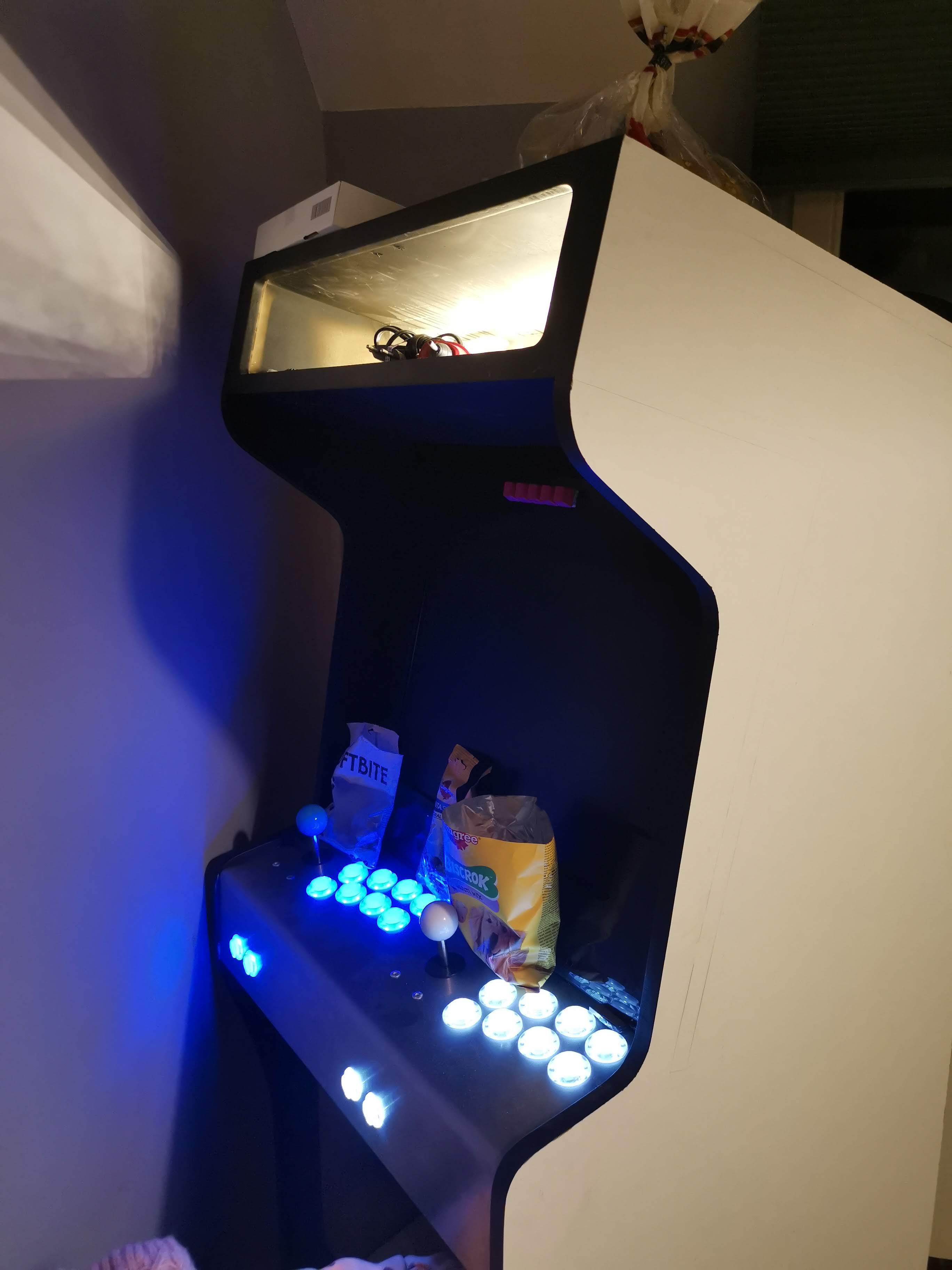
- Marquee LED backlight
- Controls backlight
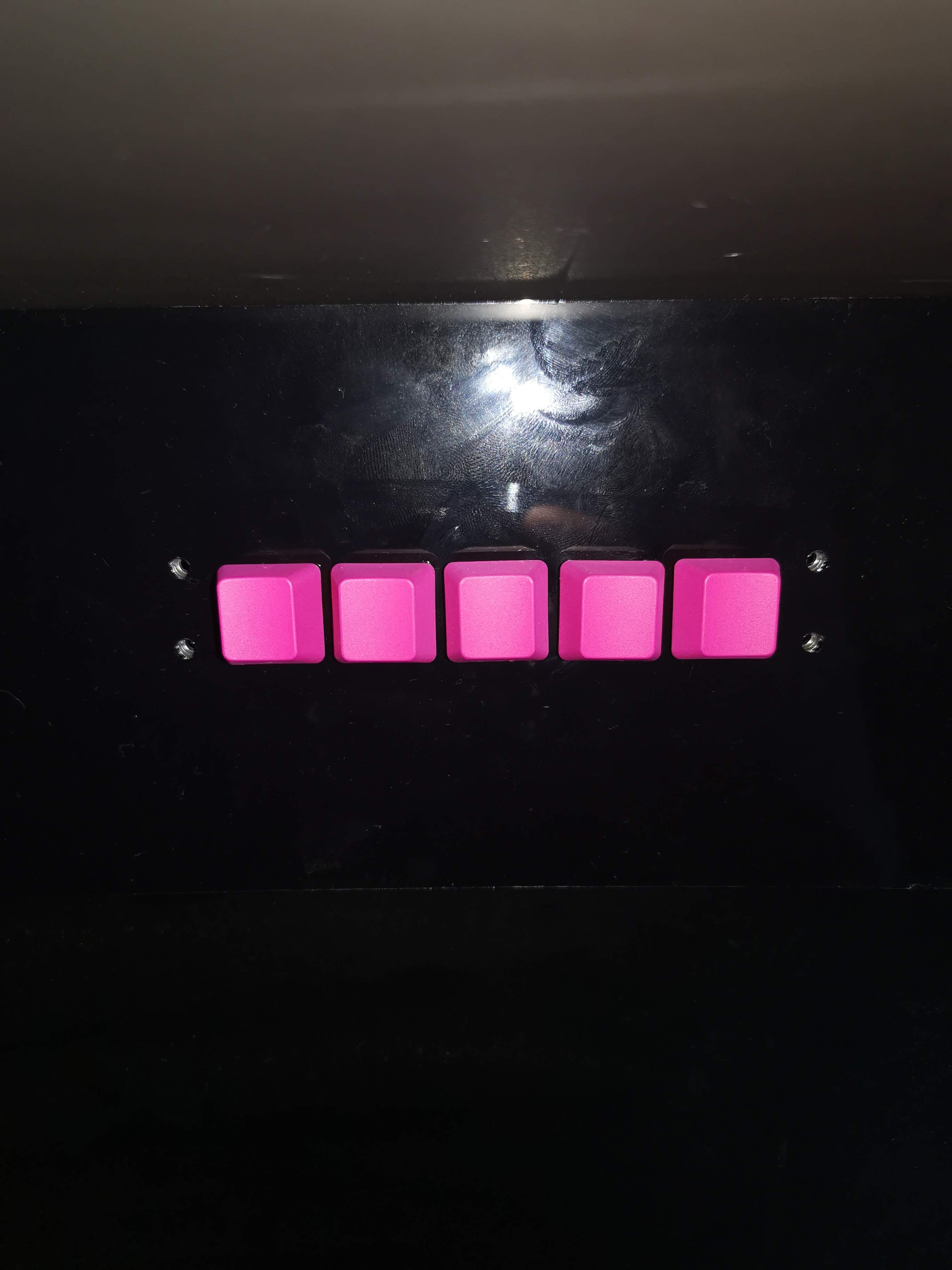
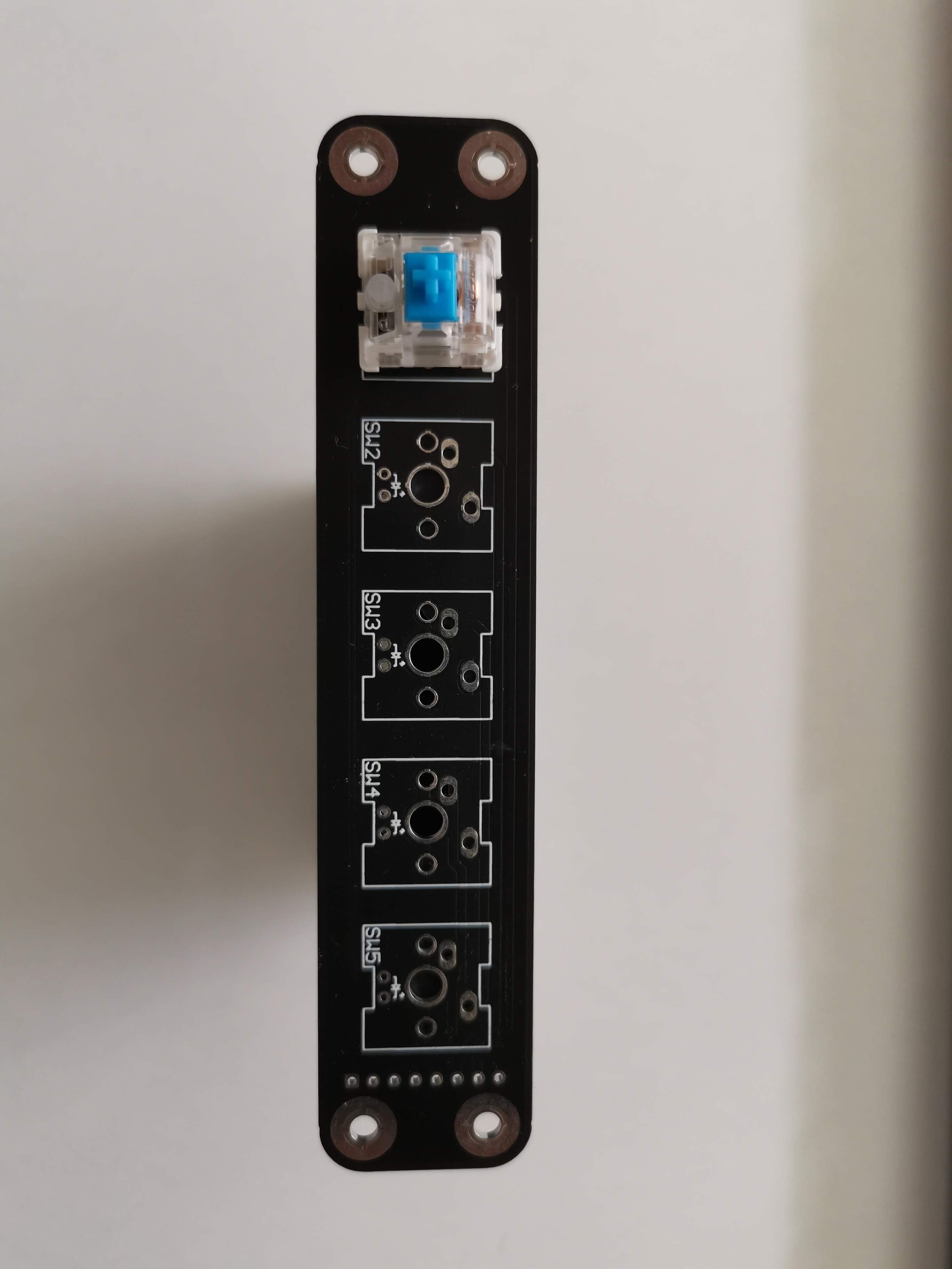
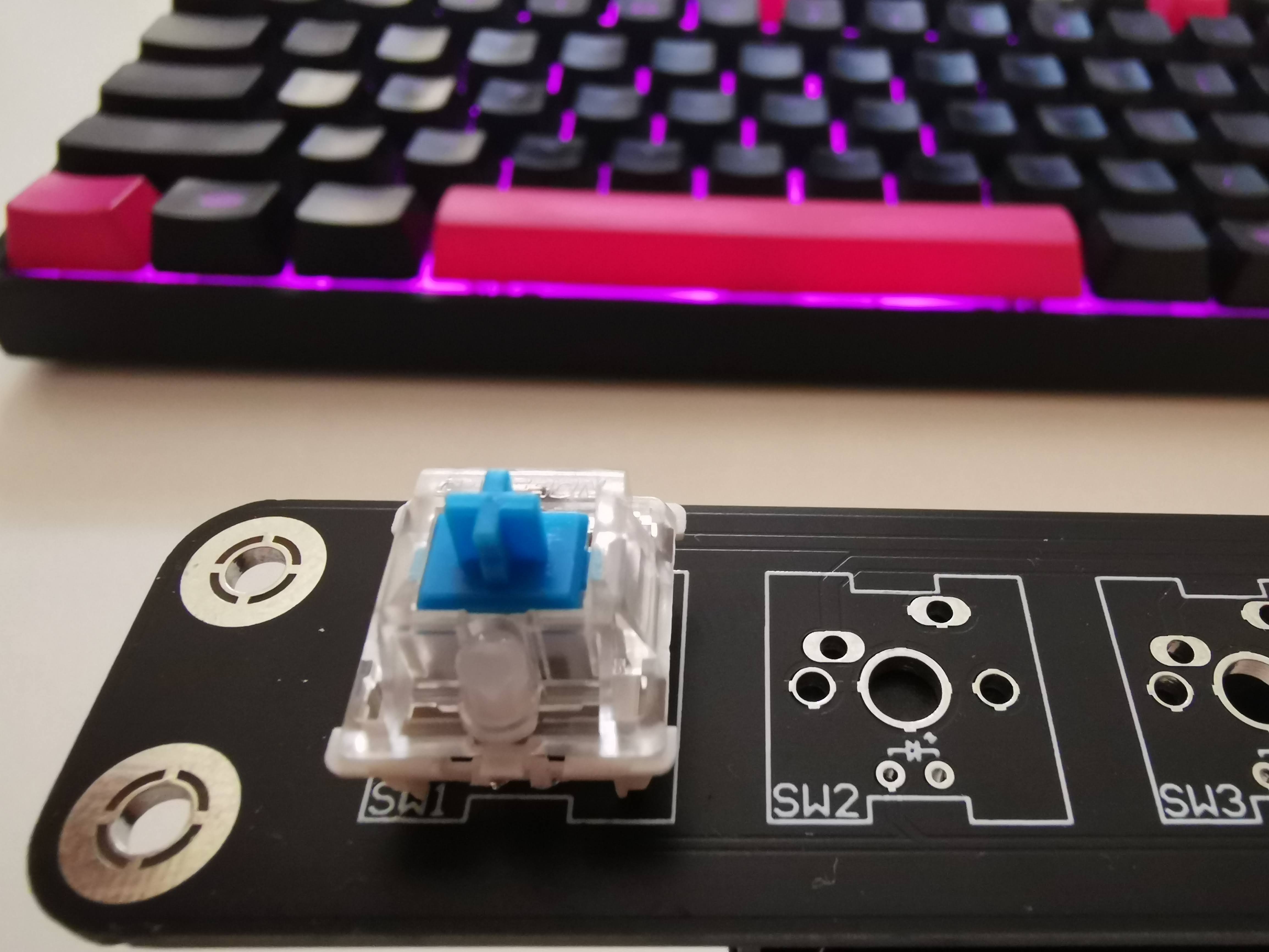
- Front panel keypad
- Raspberry PI 3
How it all works? Basically, front panel keypad controls latching relay module, 3 of available 4 channels, this is channel assignment:
- CH1 => Marquee LED backlight
- CH2 => Audio amplifier power
- CH3 => Controls backlight
- CH4 => FREE
Remaining 2 buttons on front panel keypad are connected directly to RPI GPIO port, and control the audio volume.
Power supply is distributed across all the components, including RPI and front panel keypad backlight.
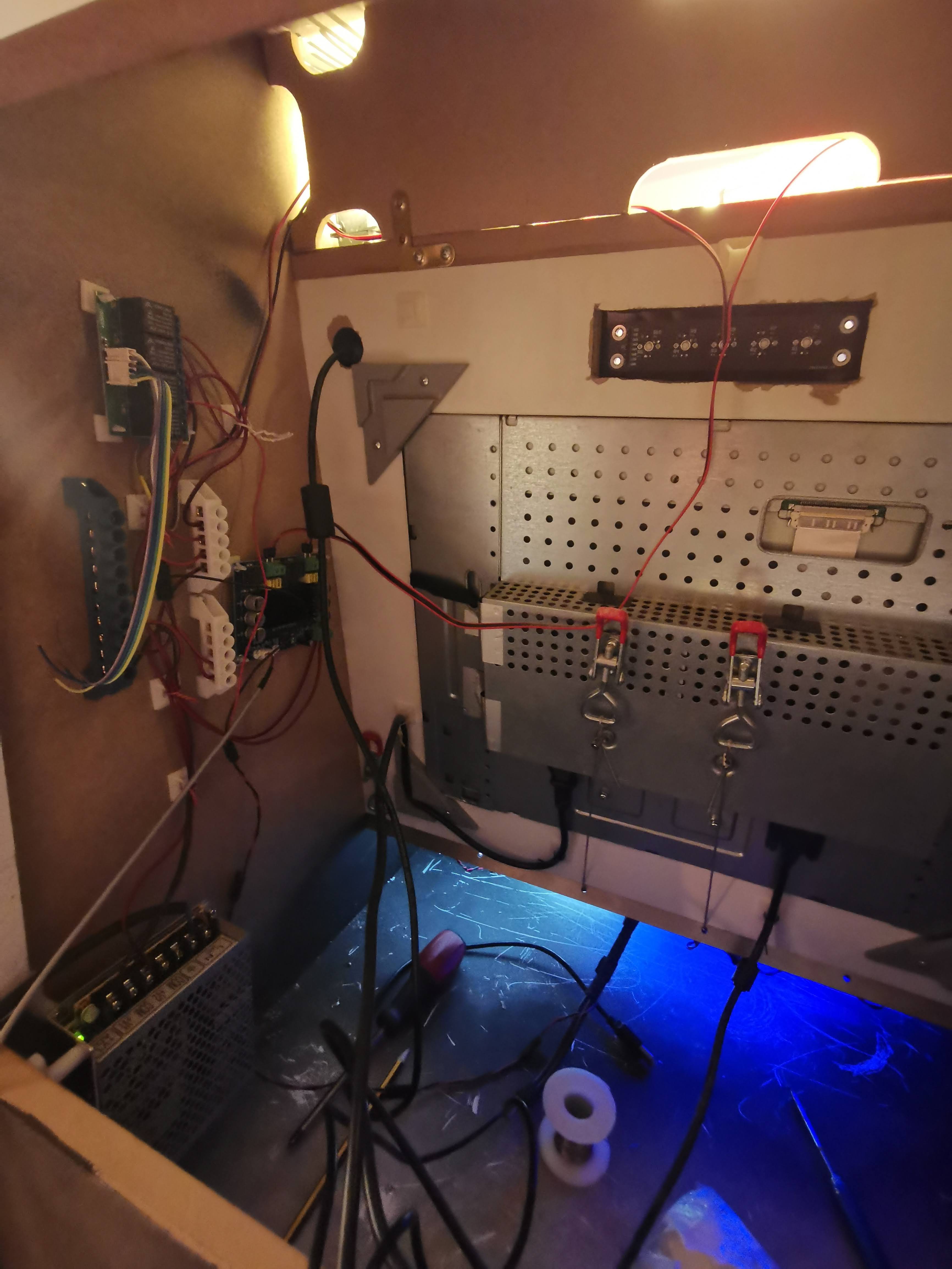
Audio signals are also wired, directly to RPI 3.5mm audio connector, using custom made coax cable, including audio amplifier input and microphone mounted to marquee plate (To enable Google assistant support).
Next items on my check list are to create graphics, and replace RPI 3 with RPI 4 (This will enable Google assistant support and Wi-Fi connectivity)
Here are some photos
Discussions
Become a Hackaday.io Member
Create an account to leave a comment. Already have an account? Log In.