 MaBe42
I started on a breadboard with the simple 555 circuit to find out roughly which R/C pairs would be suitable for the frequency range. Initial calculations using the information from the datasheet helped, too. Adding a LM358 and a CNY70 I found a way of implementing a variable gain amplifier such that the signal at the output was low enough that I could not hear it on the speaker when nothing was close to the CNY70. Choosing the 220k resistor a got some dynamics and finally saturated the amplifier. Working with square waves is easy. A sine wave would require much more work.
With the circuit being finalized, I built a first prototype. It took me more than two hours to build. But it worked. There's a video of the testing in the files section. The design was somehow resembling a piano key. However, I figured out that it would be rather difficult to implement many of it into the final circuit (output near the CNY70, supply and ground in the same plane).
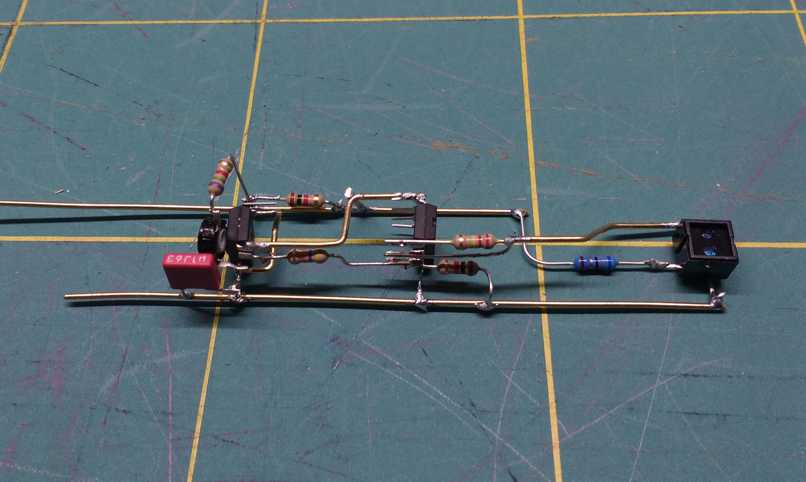
So keeping basic arrangements of the components I developed another design.
Discussions
Become a Hackaday.io Member
Create an account to leave a comment. Already have an account? Log In.