 Piotr Wasilewski
Hi!
It's been quite some time since I last wrote a project log, however this was mostly caused by shipping problems of my new actuator PCBs as well as some exams and projects going on on my university.
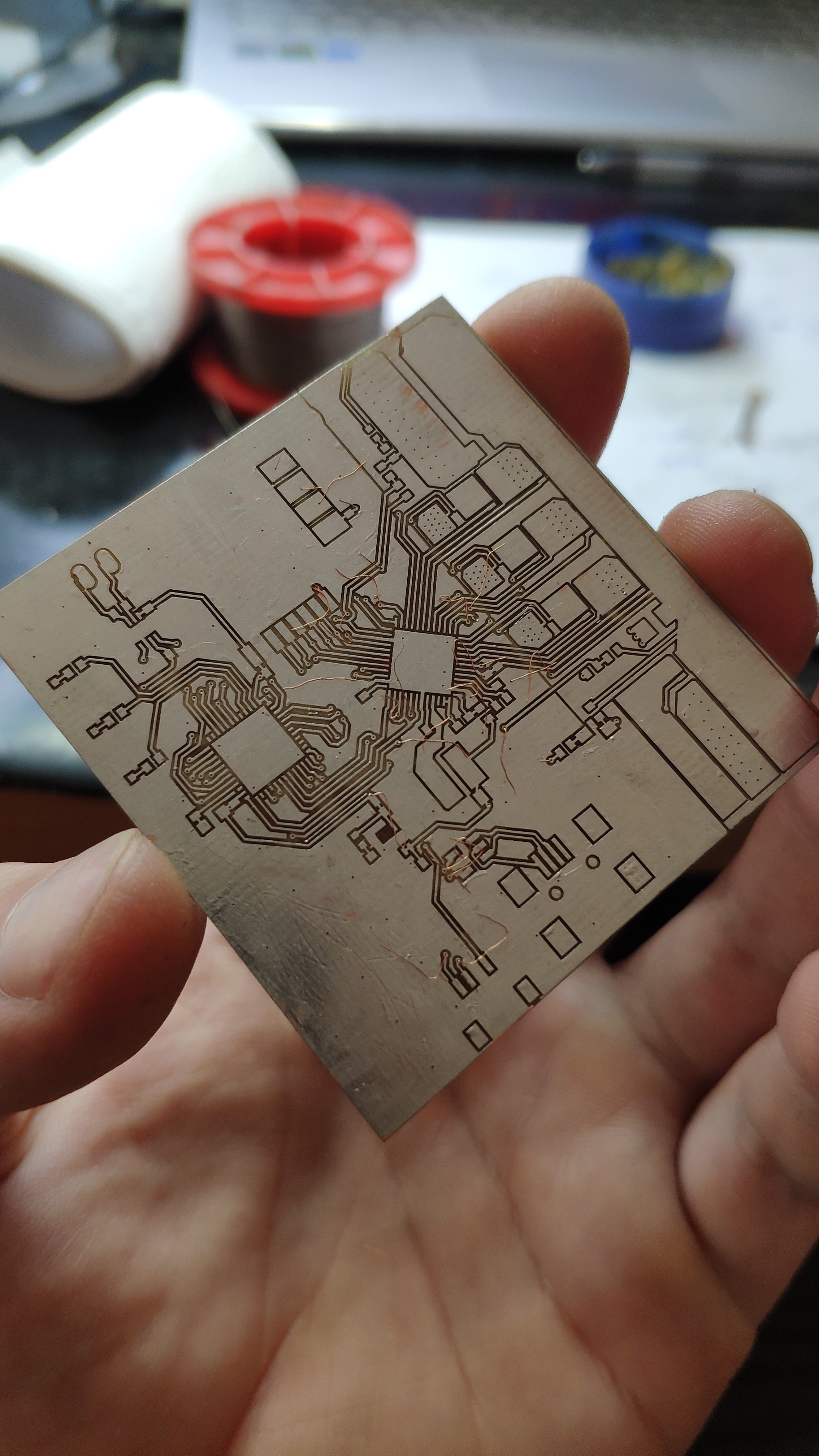
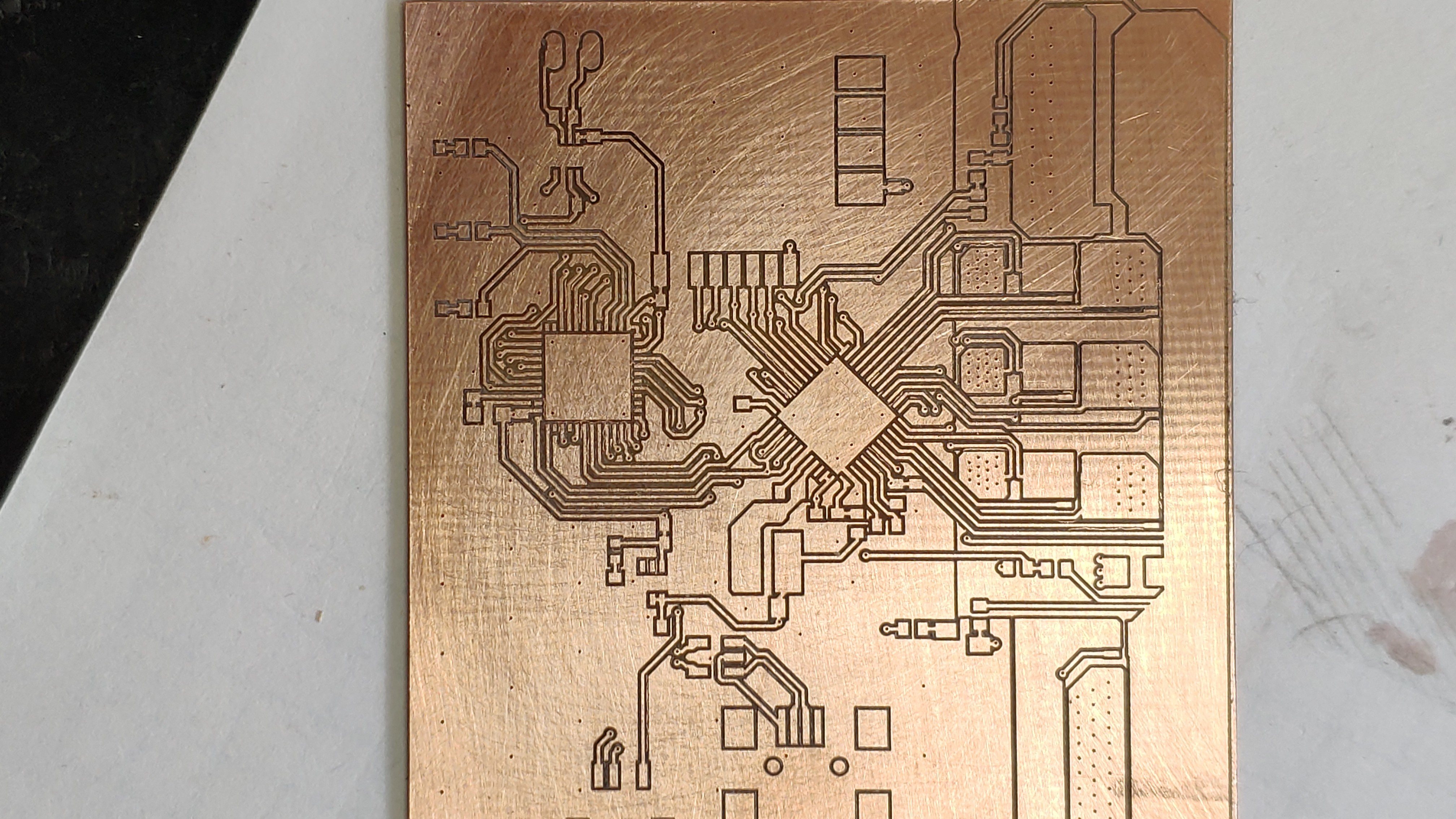
I do not like to waste my time so in the meantime I started working on a small size dyno for characterizing small motors (without the gearbox, so the load capacity is not very big). I made my own dynamic torque transducer and a small frame for the sensor. The motors (absorber and test motor) are mounted on each side of a small plate and their shafts are connected to the torque sensor's shaft through couplers. As I was sick of waiting for the PCB's to arrive I decided to mill a similar 2-layer board with a chopper functionality, to make it possible to operate as an absorber (not only a motor controller). This functionality is going to be used on the absorber motor in order to dissipate the energy produced by the motor under test. Besides I added USB connection for exchanging the data with the computer and a communication module for communicating with torque transducer. I found out that I was missing a pullup resistor on a MOSI line of the MOSFET driver, so it's good that I tested it before reordering the PCBs.
A few photos of the prototype board:
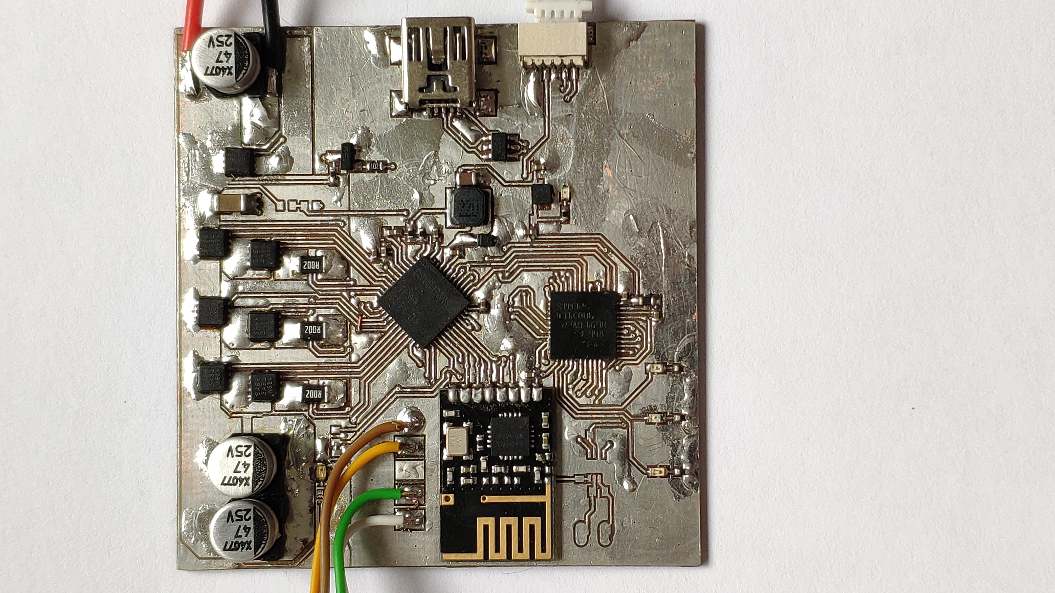
I'm still working on the code, but for now I managed to spin the motor, read currents and read velocity in a slightly different manner than before. I'm using the method of measuring time between encoder pulses using two timers. This was introduced on Ben Katz's blog a few years back. However in contrast to the software filtering technique he has used, I used the FMAC peripheral. This is a new peripheral that comes with the G4 series and it seems to work just fine. It is a simple FIR filter (moving average) but it seems to be a bit faster than it's software equivalent.
Discussions
Become a Hackaday.io Member
Create an account to leave a comment. Already have an account? Log In.