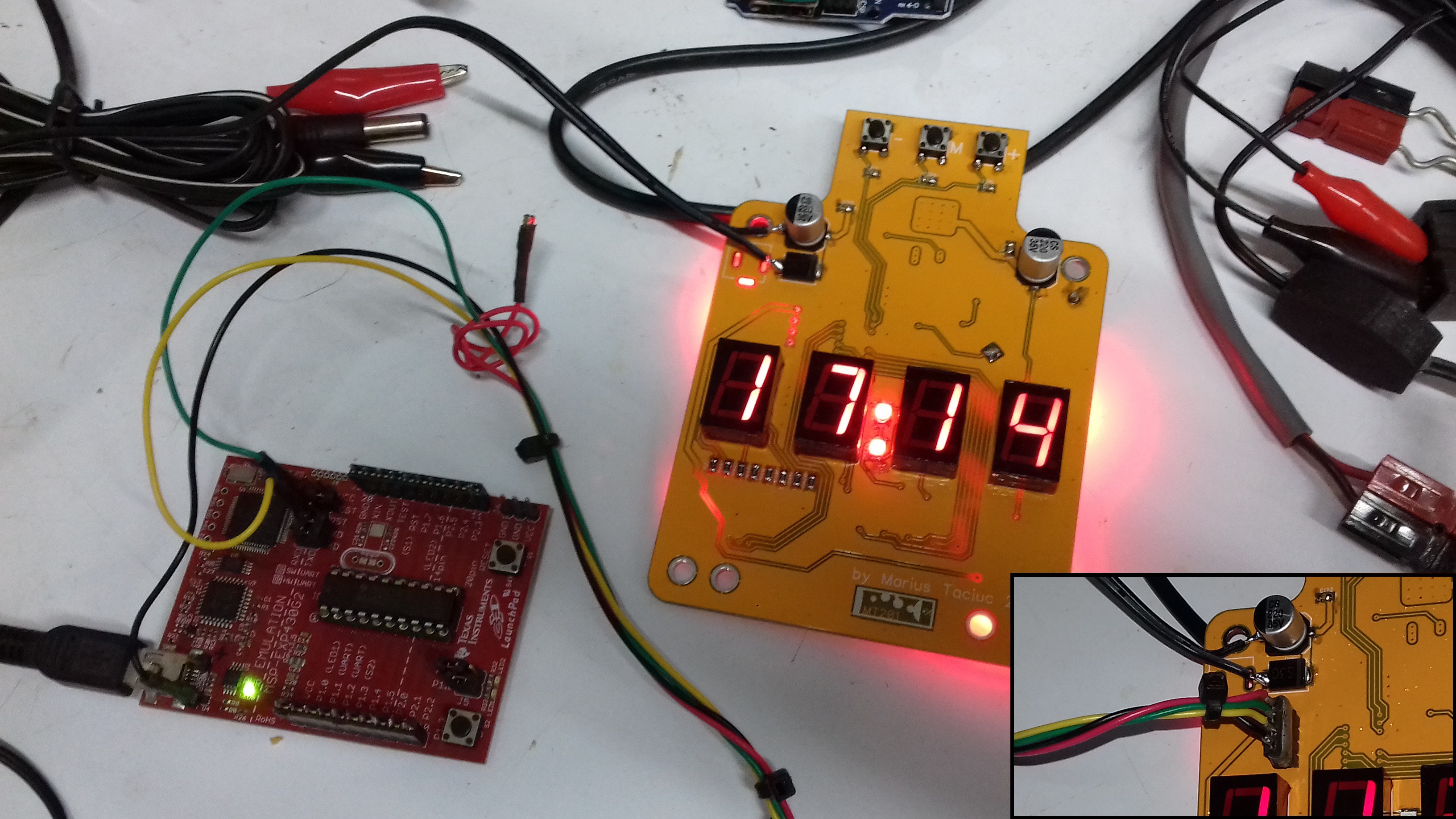
I added the firmware into the Files section. Use the MSP430 launchpad like seen in the image:

The green wire is TEST and the yellow one is RST.
The programming header is a 4 pin DIP connector with the following order:
---- red ----
-- green---
-- yellow -
-- black --
Connect the black (GND) to the square pad hole on the board. The red wire usually stays disconnected from the launchpad. In this case, the clock needs the external power to be connected to it during programming and debugging.
 Marius Taciuc
Discussions
Become a Hackaday.io Member
Create an account to leave a comment. Already have an account? Log In.