Background Story
One day, "The Signal Path" channel published this very informative video about a Lock-In Amplifier (LIA):
Since then, I always wanted to have one, fascinated by the amazing performance of such an instrument.
Once the main principles understood, I realized that the same functionality can be achieved with nothing but an oscilloscope with trace averaging mode.
Theory
A lock-in amplifier is an instrument to measure very small AC signals flooded with noise. A lock-in amplifier is able to clean up signals many times smaller than the noise, and measure their amplitude and phase.
To achieve that, it needs a clean reference signal that is synchronous with the small one we want to measure. The amplitude of the reference signal is irrelevant, same for the phase, just that the reference signal must be synchronous and clean.

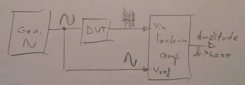
The typical arrangement is like this: A generator of clean signal is feeding both the device under test and the reference input, while the small signal flooded in noise (that gets out from the device under test) is fed to the measuring input of the lock-in amplifier. At the output we will get the phase and the amplitude of the small signal.

The trick to achieve this is that the lock-in amplifier averages many periods of the signal, so the noise will average to zero. The signal of interest will average to zero, too, except that the averaging is made synchronous with the small signal of interest (that is why it needs a clean synchronous reference signal). As a result, the noise averages to zero, while the signal of interest averages to itself (stays the same).
Thus, all the noise is removed while the small signal of interest remains, because the small signal was synchronous with the averaging process.
Usually this functionality is implemented with analog multipliers followed by integrator circuits, sometimes by simply switching the polarity (multiply with +1/-1) followed by integrator, sometimes is made purely digital by DSP.
Practice
We will implement a lock-in amplifier with an oscilloscope, by synchronizing the oscilloscope on the clean Vref (Ch2), while feeding the small noisy signal to Channel 1, then setting the acquisition mode on Average (between consecutive traces), on DS1054Z by pressing Acquire -> Mode -> Average.
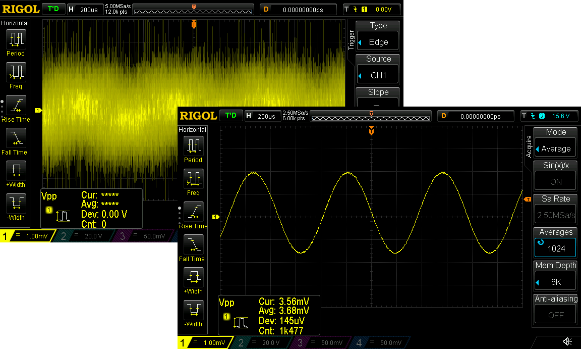
To learn how effective this is, here is the same signal before and after applying the described technique:

All the noise has vanished because by synchronous averaging, the signal to noise ratio improves by √N times (square root of N), where N is the number of averaged traces (here 1024).
If it were to look for the main blocks of a lock-in amplifier when using the oscilloscope instead, the multiplication here is made with 0/1 (by the triggering circuit) and the integration is made by the trace averaging mode (also there is no need to get the quadrature reference signal, since the multiplication and averaging happens for each and every ADC sample, including t=0, or t=pi/2, or any other point on the trace).
As a bonus, this kind of lock-in amplifier not only gives the amplitude and phase, but also shows the waveform of the small signal, which might be a big advantage, and also can work at much higher frequencies. As a drawback, an oscilloscope might not have such a big dynamic range as a dedicated lock-in amplifier.
However, the range of application for this technique is almost as big as for a dedicated Lock-In Amplifier, yet at no extra cost.
Since the Lock-In Amplifier is the workhorse in almost any research lab, there are plenty of applications for it to be used in a maker/electronics/metrology lab, too, and we will see a few handy tricks in the next projects to come.
 RoGeorge

 Ringo2k
 Martin
 Gina Collecchia