 ThinkLearnDo
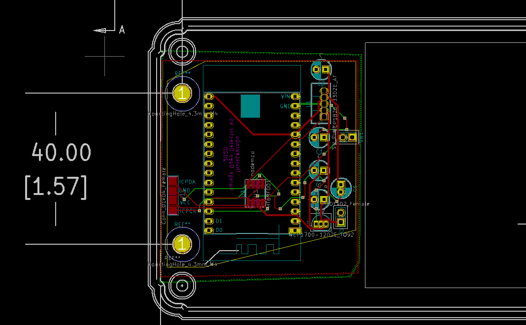
I used Kicad to put my first version of the circuit board together. I wanted to have this fit a case I found on mouser, so I needed to come up with a way to make sure the mounting holes would fit the case.
Luckily the webpage for the case I picked out, https://www.hammfg.com/part/RL6215, had a dwg version of the case. I took that and coverted it into a dxf file, which I was then able to import into PCBNew. Then when I put in the mounting holes, I just had to make sure they lined up with the image.
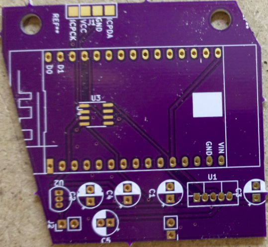
After I got the boards I was happy the holes match up correctly. Sadly, I made the mounting hole too large. I had to use some washers to make sure the screws wouldn't pull through. I'll have to fix that on the next revision.
Another thing I screwed up on this board version, was I forgot to mark the + and - on the battery connector spot.
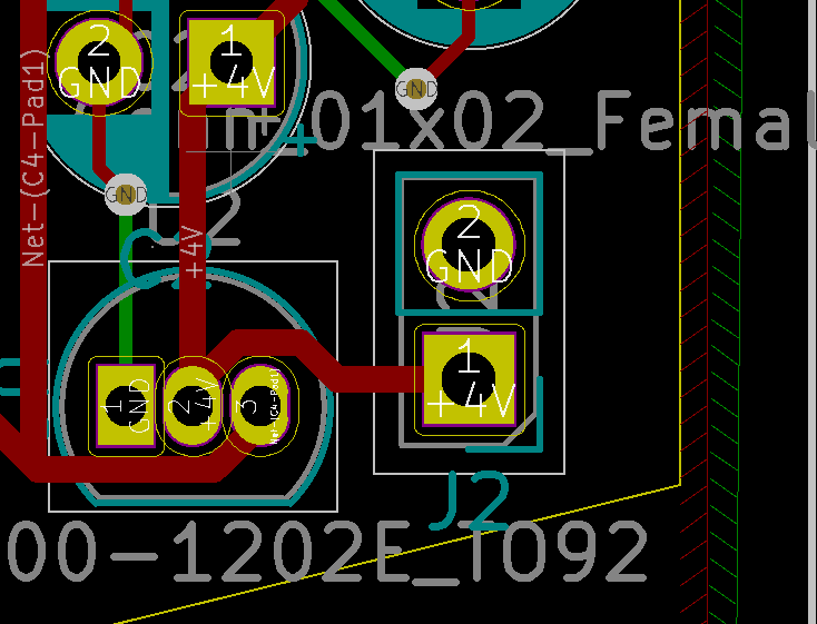
So thats another thing I'll have to fix on the next board revision.
All in all I'm pretty happy with how the board turned out.
Next up I'll need to get it assembled and try it out.
Discussions
Become a Hackaday.io Member
Create an account to leave a comment. Already have an account? Log In.