Close
0%
0%

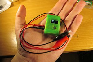
Very precise thermometer

with the University math that I never applied

Similar projects worth following
During the University years I had a lot of special mathematics classes. Back then I was rarely able to picture a real instance of when these hypothetical mathematical formulas would apply in real life and I would need them. Back then we were studying a course named "The Theory of Systems" and its main purpose was to teach us how to interpret what is inside of a black box based on only the input and the output functions. We then had to determine the transfer function or to find the closest mathematical model that would cause that response.

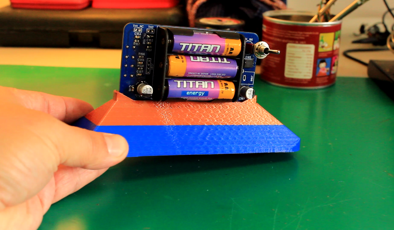
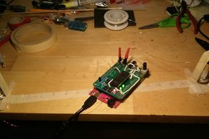
The stand support in the picture can be downloaded here:

https://cults3d.com/en/3d-model/tool/very-precise-thermometer-stand

I've been playing with microcontrollers for many years now. In the years 2000, when I had to create a thermometer using ASM code, I was usually including a conversion chart in the software. Meaning that for every read value returned by the ADC, I was assigning a temperature value. I was always including the external thermistor into a voltage divider and I was reading a proportional voltage on the input pin. This software returned value had to be something between 0 and 1023. If, for instance, I was reading a value of 485, the PC registry of my microcontroller was going into the chart at the respective line and it was returning the temperature value of 22.41 Celsius. 
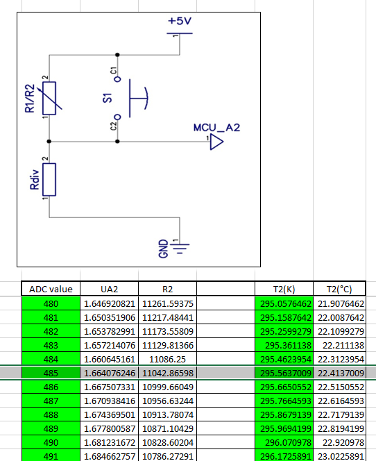
This was a very meticulous job and since I was also using some old thermistors with no datasheet, I sometimes had to sample the values of the thermistor myself and to create the sw conversion chart by hand. After a few years when the technology evolved and the C++ microcontrollers started to be very cheap and available to the masses, I realized for the first time that I can embed the transfer function of the thermistor into the software of the device. This is not only saving me the time to calculate and create the conversion chart by hand, but it can also calculate floating point results with an astonishing precision and a very large number of decimals. 

I then inserted the Steinhart & Hart Equation into the code and once I had the transfer function there, magic started to happen. For the first time in my life I was able to apply in a real manner all the things I have once learned about transfer functions during Special Math classes. I realized back then, the Electrical Engineering world would have never been the same without this scientific chapter. At least for me. 

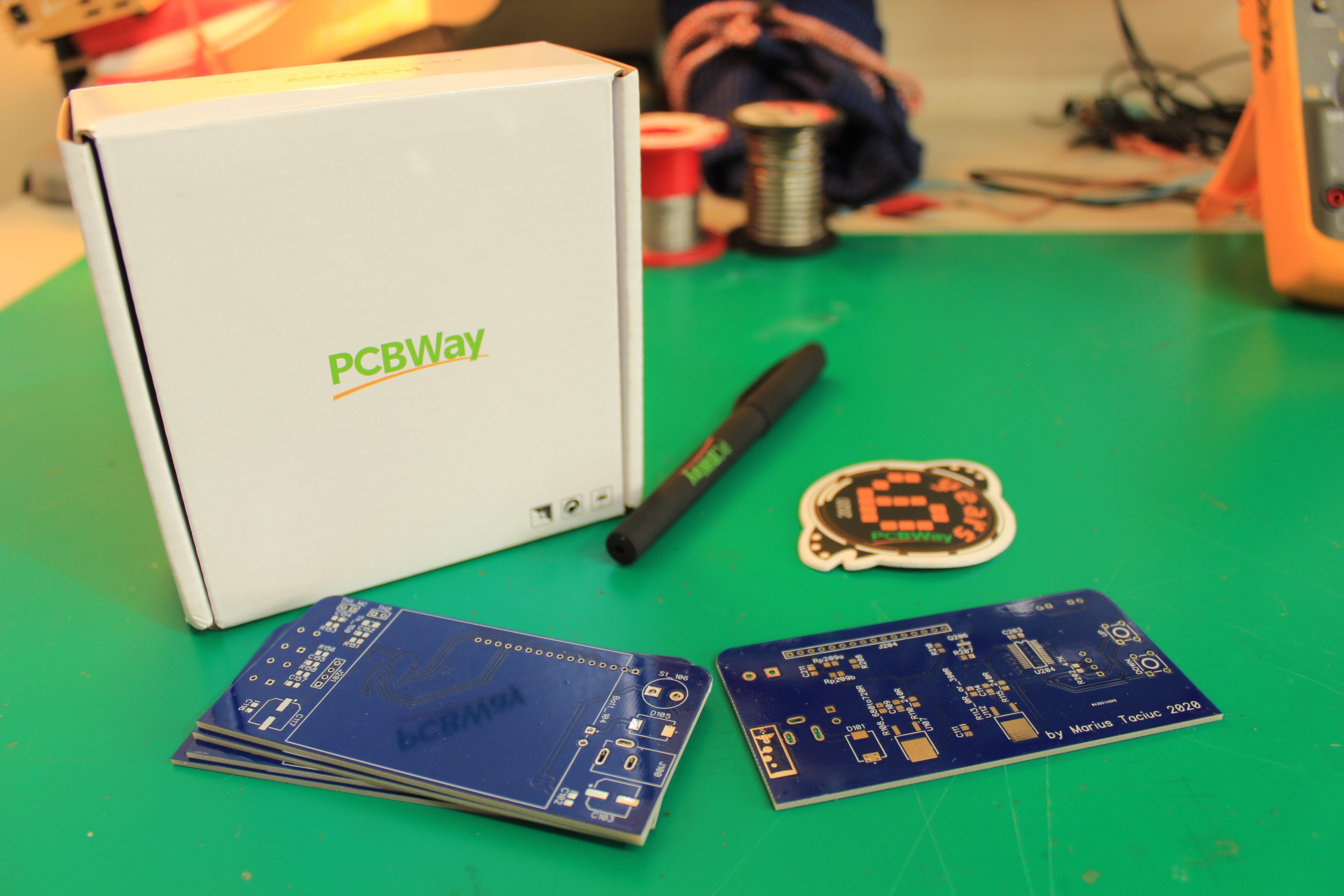
Once I received the PCB's I assembled everything by hand. 
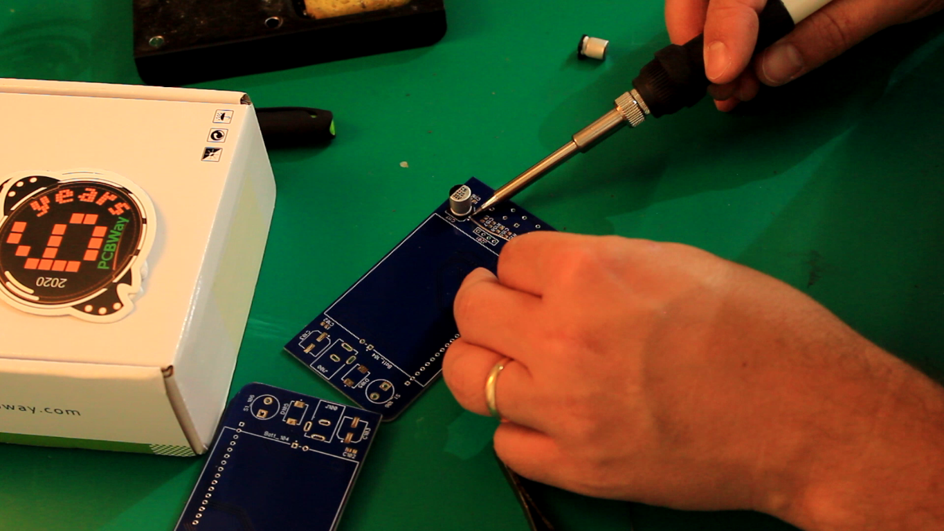
The official sponsor of this project is PCBway.com . For ordering your copy of these PCBs today, please follow the quick side link or visit the Instructions section for more details.  

VPT_update_code_16Mar2021.txt

Latest firmware that shows both the internal and the external temperatures on the same screen. Check the photo gallery for the image of this version. In this firmware iteration, the buttons are not used. I assigned them in software to move a dot on the screen, but they need no longer to be populated.

plain - 17.95 kB - 03/17/2021 at 14:06

Download

VPT_update_code_14dec.txt

plain - 21.63 kB - 12/14/2020 at 12:31

Download

VPT_update_code_28nov.txt

plain - 24.29 kB - 12/08/2020 at 05:51

Download

T_thermistor math model.xlsx

sheet - 86.52 kB - 12/08/2020 at 05:47

Download

Very precise thermometer 2020_A2_no_disp.dip

Layout - open with DipTrace

dip - 362.11 kB - 12/03/2020 at 02:45

Download

View all 7 files

  • Fail on choosing the proper battery type

    Marius Taciuc12/20/2020 at 10:41 0 comments

    Notice that in the video and in some of the pictures I have that 3xAA battery pack at the back. It is meant to power the whole thermometer when the power jack is not connected. The user just has to flip the switch on and it should work normally. It seems like I made a design mistake and it will not work with a 4.5V input, because of the voltage dropout on the linear power supplies. For some reasons, the actual dropout in the voltage is more than 1V on both the input diode and the LM317 and at the input of the 1117 I get less than 3V. This is not enough for powering the microcontroller so it doesn't work. If you want to replicate this project, you will have to replace the battery pack with a 9V battery holder. 

    This is also very ironic, considering the level of engineering I aim for in this project. Lol. Mistakes happen and I guess this is exactly the kind of trial an error that propel us forward. 

  • How precise this thing actually is?

    Marius Taciuc12/08/2020 at 05:45 0 comments

    Well, we have to consider that the components are not perfect. The manufacturer says that the thermistor is having a 1% tolerance. Judging by the piece of code I posted at the first project log, the following parameters are influencing the final result: input voltage, tolerance of the fixed voltage divider resistance and the tolerance of the thermistor. In reality there will be other factors like: the tolerance of the oscillator of the microcontroller, the voltage dropout on the traces, the temperature drift of other components, tolerances of the internal ADC converter inside the controller, etc. If everything else was perfect and I would only have to deal with the tolerance of the thermistor, how much would that influence the final result? I mean, if I have a 1% tolerance thermistor, would the final measurement vary with 1%, more or less?

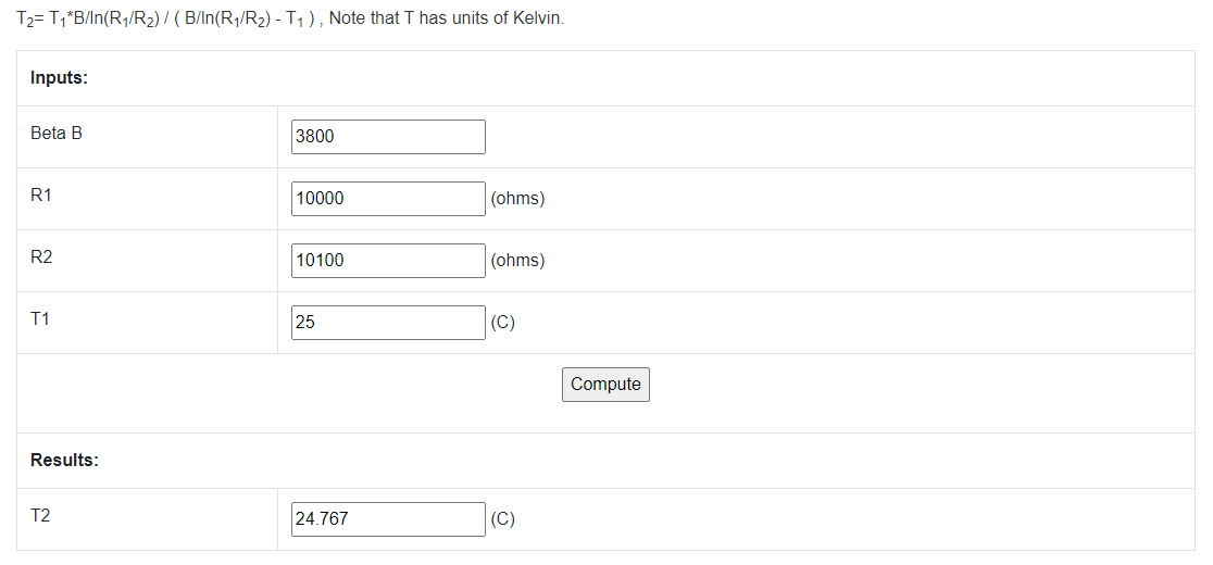
    To find out the answer for 25⁰C (for example) we just go to the online calculator and we input the following parameters:

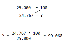
    In this case, R1 is what the thermistor should have at 25⁰C and R2 is what the thermistor actually has. I modified R2 at its maximum error. 1% tolerance means that the component can either be 99% or 101% of the total value of 10KΩ at maximum error. The expected result should normally be 25, but instead it is 24.767⁰C. We can apply the law of three here:


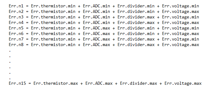
    So the total error of the final result based on only the maximum tolerance of the thermistor is less than 1% in this case. Similar to this example, maximum errors can be calculated for each element in the chain I mentioned above. Later on, all of these errors can be summed up together in a single equation:


    And of course, all of these formulas can be written in a Mathcad sheet (Matlab or even Excel can be used) in order to be able to elegantly play with the numbers in real time. Of course, the above equation only reveals what happens when all of the errors go one way, but most of the times in a similar chain of errors we also have some that cancel each other. Considering the fact that, for instance, Err.thermistor can take at some point in time any value between 99% and 101%, thus this error can be anything from a min to a max, we could include all of these minimums and maximums into a giant model. A model that would include all the minimums and maximums of all the other errors. So for a better mathematical representation of the total error we can write a matrix that would be something like this:

    Then we can analyze which is the maximum Err.n and have that reported at the end of the worksheet. Many times, these mathematical models can also reveal what happens with the circuit if one of the components goes bad or out of calibration. A complete worksheet like that is also sometimes called Risk Analysis study, Failure prediction or Component case study. Here is where rocket science starts to happen as this risk analysis study can take on a whole new dimension based on the complexity of the transfer functions of all the components on that board. I mean, in this example it seems simple because I am only dealing with serial resistors and a thermistor, but imagine an electronic module meant to equip vehicles, aircrafts or even space probes. Almost all of the major companies like Tesla, Boeing, Nasa and many others are playing with the transfer functions like that and creating these risk analysis. The higher the required safety level is, the deeper and more complex the math model analysis goes.  

    That is not all. This thermometer does not limit itself to having a small, predefined error. Maybe you were wondering why I declared Rdiv to be 9950 ohms (instead of 10K) in the C++ software section I posted a few days ago. It is because I have the possibility of measuring these components with a very precise ohmmeter before inserting them into the schematic and that can result in calculating and obtaining even a smaller error than 1%. In order to achieve a very precise thermometer...

    Read more »

  • The implemented SW formula

    Marius Taciuc11/25/2020 at 06:41 1 comment

    Between the Lagrange’s theorem and the Laplace transform, nabla and delta symbols, we were also finding transfer functions like this one. 

    The applied Steinhart-Hart Thermistor transfer function can be transcribed as:

    T2= T1*B/ln(R1/R2) / ( B/ln(R1/R2) - T1 ) 

    for known resistor values. The B (beta) parameter is also a known since I will be using thermistors that have proper documentation and online datasheets.

    The thermistor I am using is a 10K 1% (3380 Beta one) that has the datasheet here: 

    https://www.tdk-electronics.tdk.com/inf/50/db/ntc/NTC_SMD_Standard_series_0603.pdf

    For everybody who is interested in playing with this mathematical model, if this is new information to you, please have fun with this online calculator. I am not affiliated in any way with the creator of this calculator, but I though I drop this link here for who wants to learn more:

    https://daycounter.com/Calculators/Steinhart-Hart-Thermistor-Calculator.phtml

    You can also check the wikipedia official article:

    https://en.wikipedia.org/wiki/Thermistor

    My software implementation looks something like this:

    Notice that I have a special if to prevent the ln(1) which is 0. This has to be prevented in this equation or else it will turn into:

    and you will get an error there. This happens at 25 Celsius degrees and if this error is not prevented, I think it just shows 0.0000 on the screen. 

View all 3 project logs

  • 1
    Ordering PCBs

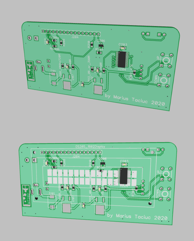
    I just added the pcb files. I created them in DipTrace and I ordered them from PCBway.com . For an easier experience, I also added a zip folder with the exact gerbers I used to order this. If you want to replicate this project for yourself, don't hesitate in ordering your pcb copy today. These guys deliver worldwide and they even send to my temporary location in Papua New Guinea. The communication with them was great and so far the PCBs were state of the art. 

View all instructions

Enjoy this project?

Share

Discussions

pe1ndo wrote 12/18/2020 at 07:33 point

very nice! I once had to use an NTC and didn't know about Steinhart Hart. After some research I found this page. which has a graph explaining where the Steinhart hart function is all about.

https://www.thinksrs.com/downloads/programs/Therm%20Calc/NTCCalibrator/NTCcalculator.htm

  Are you sure? yes | no

Marius Taciuc wrote 12/18/2020 at 07:58 point

Awesome. Thanks for posting here. 

  Are you sure? yes | no

Similar Projects

Does this project spark your interest?

Become a member to follow this project and never miss any updates