 Sebastian
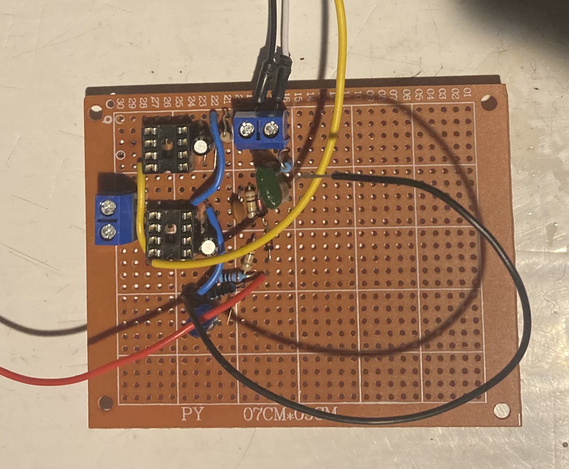
Worked on the control circuit today for the SSTC. It can be connected to an interrupter using the testing pin next to the LED, which indicates the duty cycle of the interrupter.
Originally, I wanted to use a fiber optic receiver to get the interrupter signal—but my old one broke so I’m going to use the test pin for the time being. The other screw terminals are for the feedback transformer connection and gate drive transformer connection.
Currently the driver ICs are not included so I could test the circuit before risking damage to components. I made two basic 555 oscillators—powered via 9V battery—and connected them up to the inputs on the control board, and using the scope I tested each pin for the IC sockets and it looks good to go. The next step will be testing with the ICs in and the GDT connected.
Discussions
Become a Hackaday.io Member
Create an account to leave a comment. Already have an account? Log In.