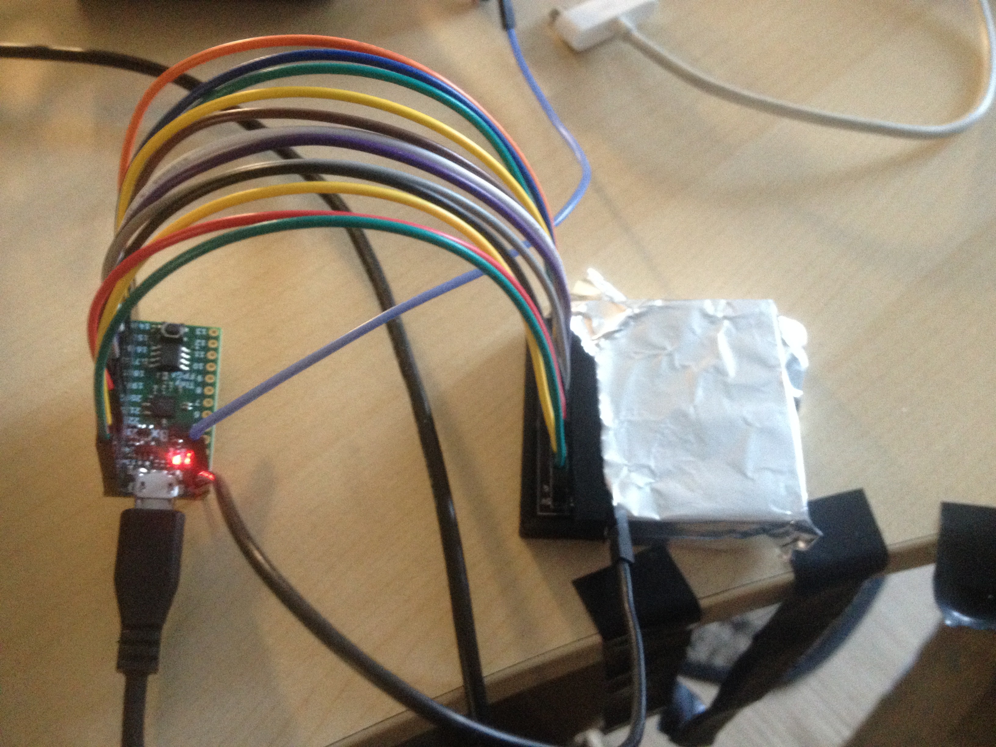
By putting some distance between the FPGA and the DDC112 board, the noise is reduced to about 5fA (100ppm at the range of 50pA). This would mean that either the inductance of the jumper wires act as a filter for the power supply and ground lines, or that EM radiant noise comming from the FPGA is reduced.
I tried to add a separate 5V power supply form a regulated 9V battery, to see if there was still some noise comming from the positive side of the power supply. With this new setup, the noise is still around 5fA, so no improvement. (Wich is good news, since I don't want to be limited to battery-supplied operation.)
To further investigate the effect of proximity of the two cards, I put back the FPGA on top of the analog card, and got still the same noise.
Adding two small inductors ( ~100nH or 1uH, I can't measure the wire inductance with my LCR meter since it's too low) in series with 5V and ground lines (or some kind of choke transformer) would probably do the same thing as the jumper wires.
Two things might help :
- A better Faraday shielding of the analog portion of the circuit.
- Complete isolation from USB ground, wether by wirelessly transmitting data (and power the circuit with a battery), or by using a whole bunch of optoisolators and power isolators. In both cases, it's a project in itself.
By placing the box inside aluminum foil, I get an alternance of values from -0.012pA to -0.016pA in a regular alternating pattern. If this systematic error was corrected, I would get a noise of about 0.5fA, or 10ppm, wich would be in good agreement of the datasheet (~10ppm at range 1 (50pC) and 50pF of input capacitance). This is probably due to the fact that the two integrators don't have exactly the same capacitance. A background correction could measure the mean of the two signals and correct accordingly.
This points me to a small bug regarding data transmission. As my code rely on the sending of a \n (ascii=10) character, sometimes I got incorrect length of string because some other byte also have this exact value. I'm not at all constrained by speed of data transfer, so doubling the number of bytes to get all the data seems the way to go.
The effect of alternating between two charge values is also seen in test mode, with the 13pC charge injected, however the amplitude is greater (0.2pC, compared to ~0.05pC when there is no signal at the input). It would be a good idea to mesure if the correction is relative or absolute. (In case of a mismatch of integrator capacitance, the effect is on gain, so it would be a percentage of the reading.)
 Frédérik Berthiaume
Discussions
Become a Hackaday.io Member
Create an account to leave a comment. Already have an account? Log In.
The jumpers are inecessary compared to a good farday cage connected to ground.
A "warmup" is necessary to obtain good stabilisation and noise reduction, in the order of ~30min (TBD). I get a noise of about 1 to 2 fA.
Are you sure? yes | no