 Tim
TimI used 9 inverters from two RINGO5 boards to build a single ring oscillator with 9 stages. Due to the lower oscillating frequency, the individual inverters are able to reach a more steady state during switching.
 The output at VDD=4.5 V is shown above. The waveform does now rather resemble a digital switching signal.
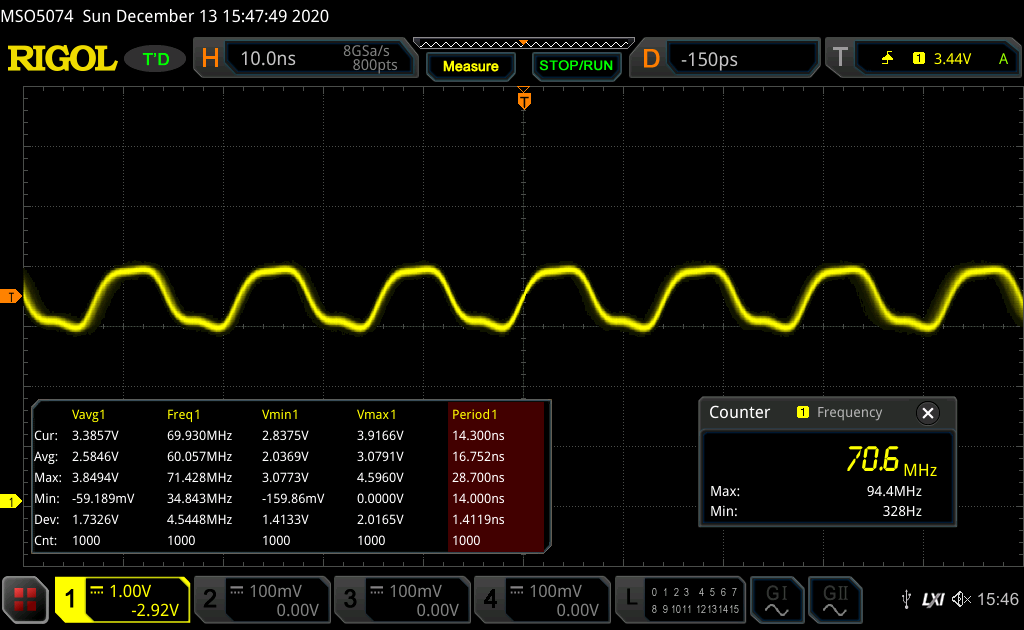
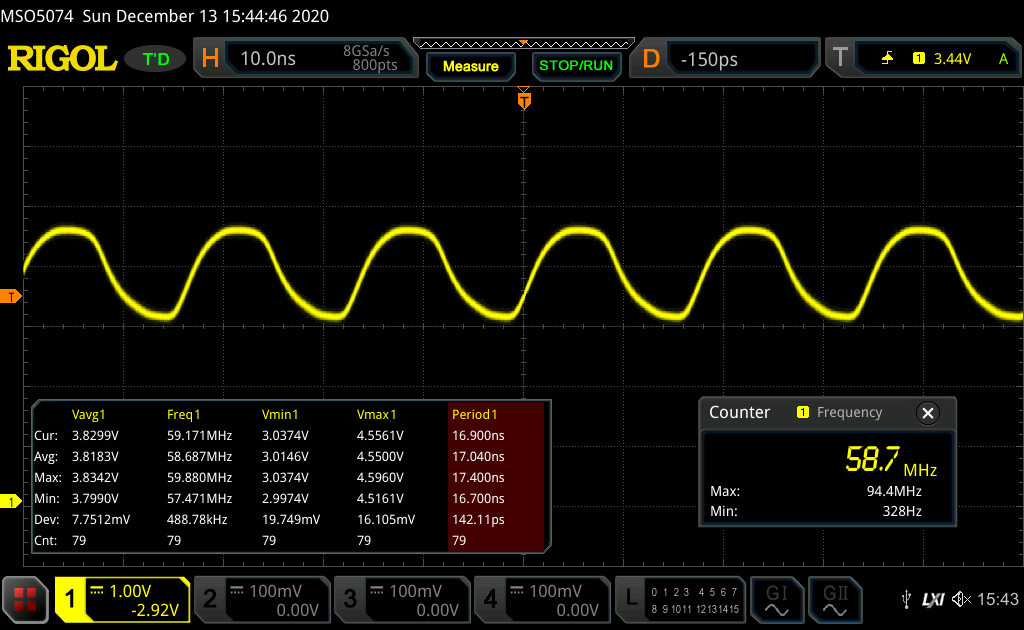 The output for VDD=5 V is above.
| Vdd [V] | Idd [mA] | Vavg [V] | Vmin [V] | Vmax [V] | Swing [V] | Freq [MHz] | tpd [ns] |
| 4.5 | 80 | 3.36 | 2.86 | 3.83 | 0.97 | 70.7 | 0.78 |
| 5 | 92 | 3.81 | 3.01 | 4.54 | 1.53 | 58.6 | 0.94 |
The tpd and logic levels are very similar for the RINGO5 and RINGO9 confirming sub 1ns tpd for the LCL inverter.
Discussions
Become a Hackaday.io Member
Create an account to leave a comment. Already have an account? Log In.