I'll try to keep it brief. You have seen me investigate several different styles of discrete logic, including the weird DTL derivative LTL.
One obvious omission was emitter coupled logic, ECL.

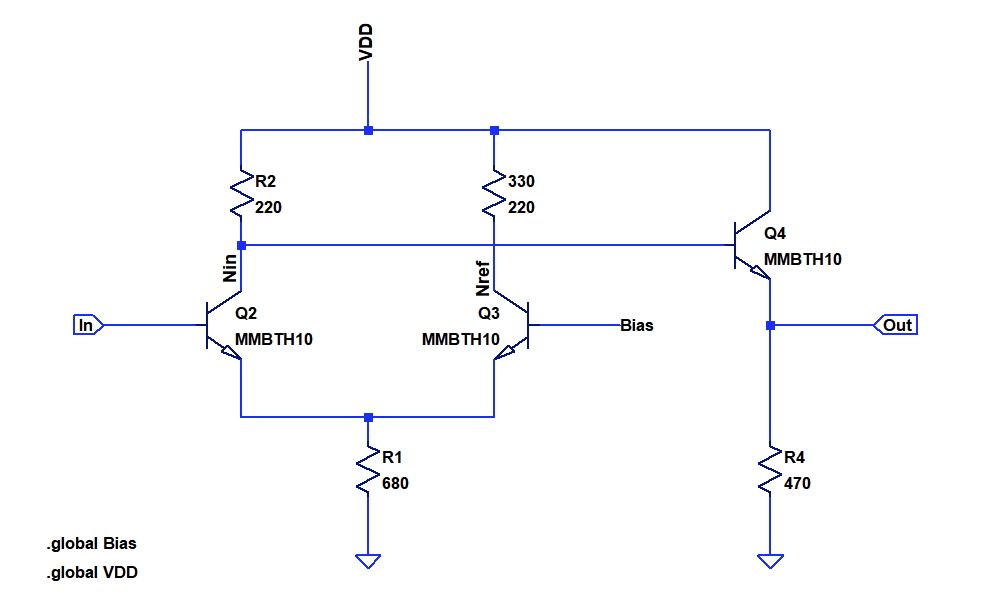
Let's ponder about the right side of the differential pair (Q3). It does not only consist of a resistor and transistor, we need a static bias reference in addition. This adds a lot of components to what could be a simple RTL or NMOS inverter.

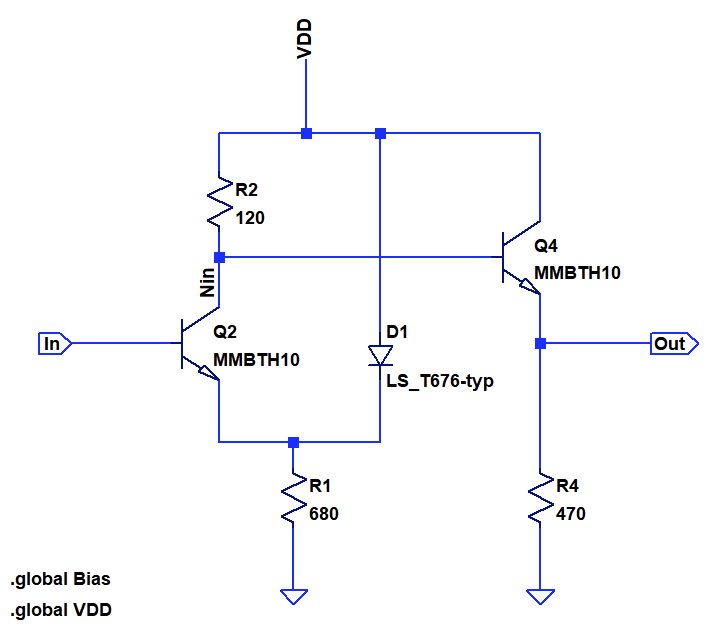
But who says we have to form a differential pair from two identical transistors? The circuit above shows an inverter formed from an assymmetric differential pair consisting of a LED and a bipolar transitor. The benefit of this is that it saves one transitor, one resistor and the bias reference.
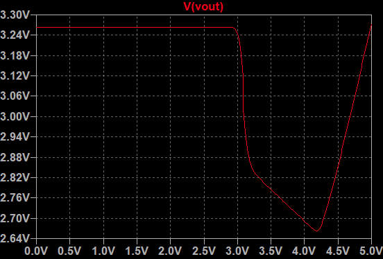
 The plot above shows the input-output relationship of the inverter. The threshold level is at 3.0V, the high level is at 3.25V, while the low level is at 2.8V. The output voltages increases again if the input is driven far above Vh. This behavior is similar to ECL.
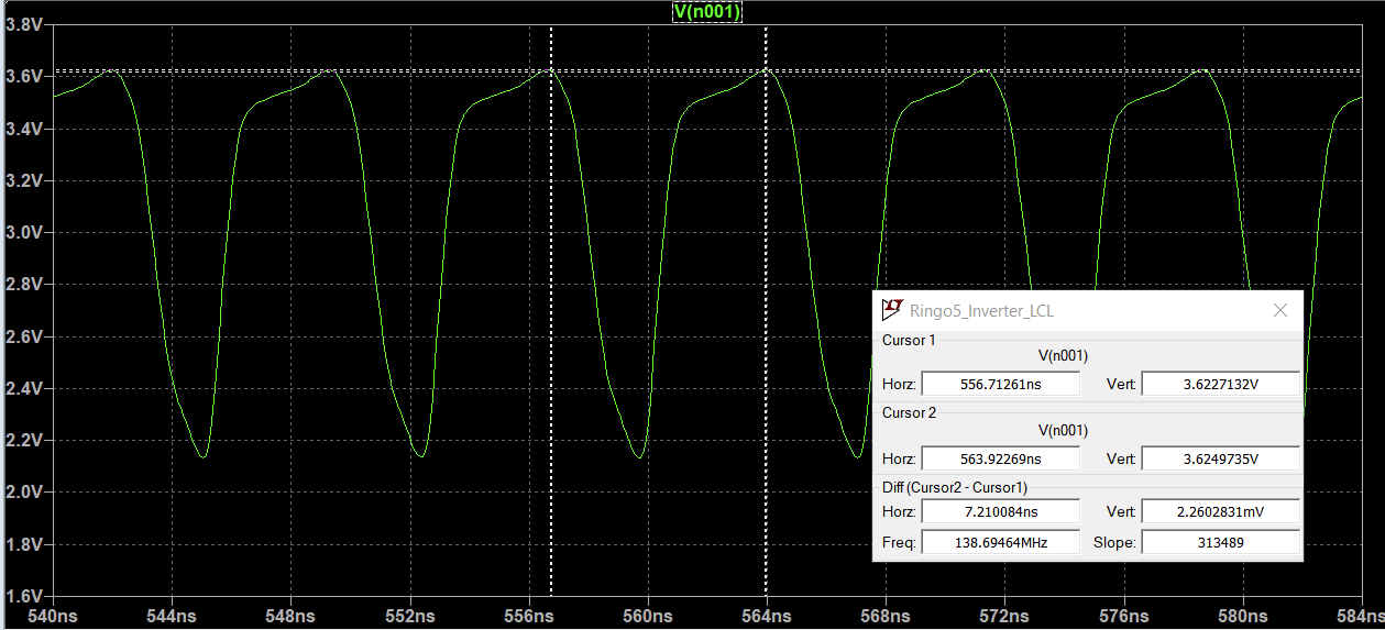
 Oscillator frequency is 138.7 MHz, which means that the tpd is 720ps. There is some overshoot, which appears to increase voltage swing.
 Just like for ECL and RTL, the basic gate for this logic style is a NOR gate. The output buffer allows combing the outputs of several gates to form a wired AND.
 Tim
Tim
Discussions
Become a Hackaday.io Member
Create an account to leave a comment. Already have an account? Log In.