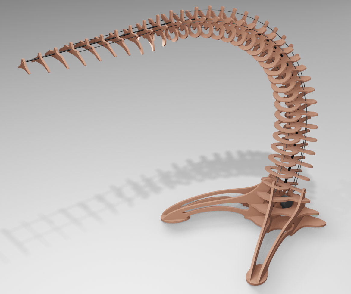
It's about the looks...
As i said previously, i was a bit hesitant on the foot design. The head and the arm part are based on the same technique but i needed some kind of 3d assemblage for the base which need to hold at least the electronics and the stepper...
I started some drafts in inkscape but i didn't managed to get satisfying results : i had a hard time visualising the 3d shape i wanted even with the "superposed" interpolation technique...

Change of process
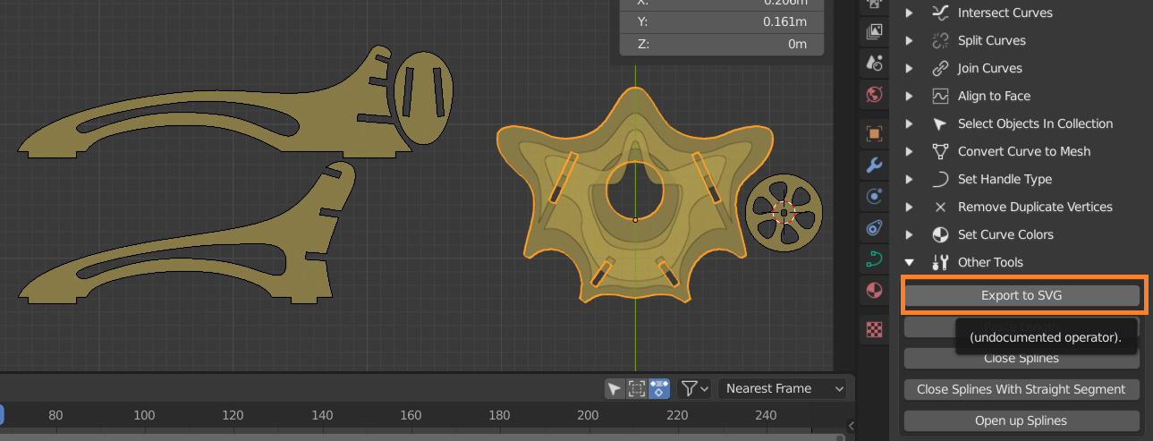
Maaybe i need to do it differently this time : what if i designed my shapes in blender instead? Before trying anything, i had to make sure that i could export them in the familiar SVG format : i found the following blender addon that allows me to export the blender bezier curves as svg https://github.com/Shriinivas/blenderbezierutils
I think i'll have to tweak the scale because it exports the shape in viewport pixel coordinates, not a big deal , i'll see later on...

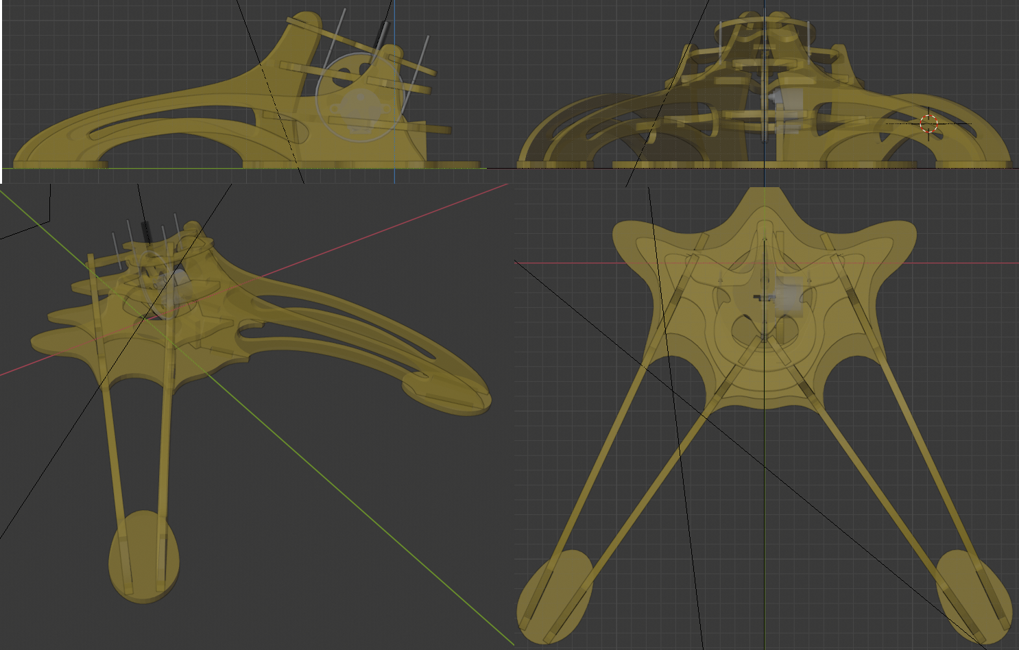
I came up with the same interpolated shape , but this time , they are progressively angled to reach 20°, which is the inclination i find appropriate . The challenge here was to find a way to intersect the legs with those interpolated shapes and assemble them with notches.
Earlier in this project i found some software that can do 2 profiles from 3D models but i don't think it would be flexible enough to do what i wanted :https://www.sculpteo.com/en/prepare-your-file-laser-cutting/slicer-fusion-360-tutorial-prepare-your-file-laser-cutting/slice-your-3d-model/
So i decided to do all of them manually, with the advantage of the 3D view to align the notches with one another.
 I used the duplicate linked feature which allows to clone a part and move/rotate it in place. When a modification occurs on one part, it is reported immediately on the other one: i have in a corner of my scene all the parts in a 2d plane that i'll be able to export at will. I don't know if fusion 360 or another cad soft can do that less painfully but i already know blender well so...
I also started to find a location for the stepper and the wheel that will control the arm. I still need to find some room to place the wemos and the stepper driver.

I think i will do a cardboard mockup to check the stability and the assembly before cutting any wood.
Discussions
Become a Hackaday.io Member
Create an account to leave a comment. Already have an account? Log In.