Close
0%
0%

Deuteron

Dauphin DTR-1 Reverse Engineering and Upgrade Project

Public Chat
Similar projects worth following
I have a few of these incredible machines from 199x.
I like these machines.
I reverse engineered them. I upgraded them beyond the specs.
Now I want to publish, what I've done.

Project consists of two tightly coupled parts: 

  • reverse engineering and documenting the DTR-1 to some degree (01 chapter)
  • upgrading the DTR-1 to the maximum, using the available information (02 chapter)

Project goal if  has three goals:

  • obtain, organize and keep information about this outstanding platform/system
  • create some hardware, that was not supposed by the vendor
  • simply have fun!

  • Internal View

    megov12/20/2020 at 23:43 0 comments

    What's inside

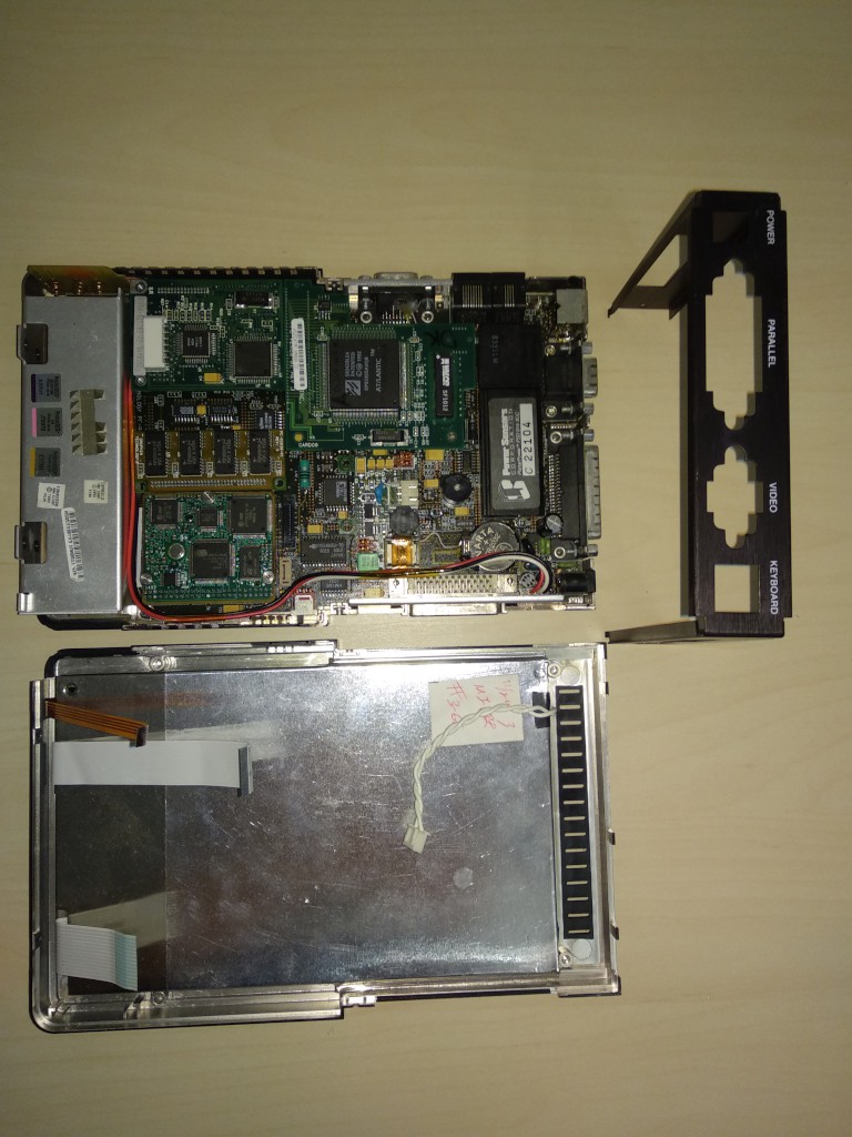
    After unscrewing the case, we're get two parts: front part holds LCD, front panel LEDs and inductive touchscreen.
    Back part holds all other devices of DTR-1 - mainboard with battery compartment and various mezzanines.
    This is the overview of the internals:

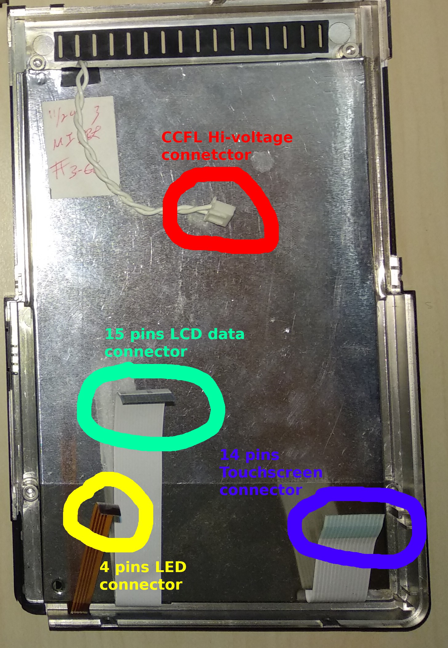
    Top part has 4 connectors: hi-voltage CCFL back light connector, front panel LEDs connector, touchscreen connector and 15 pins LCD data connector:

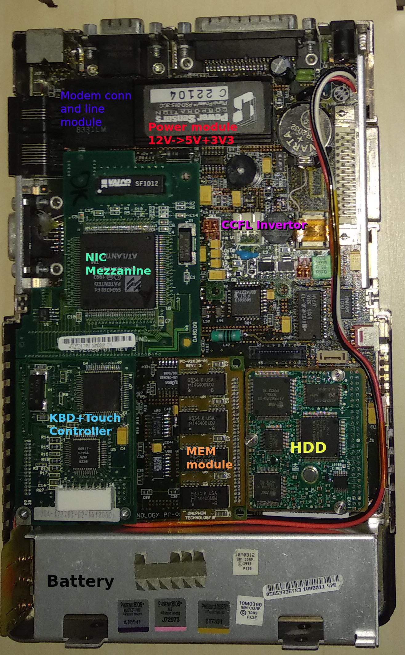
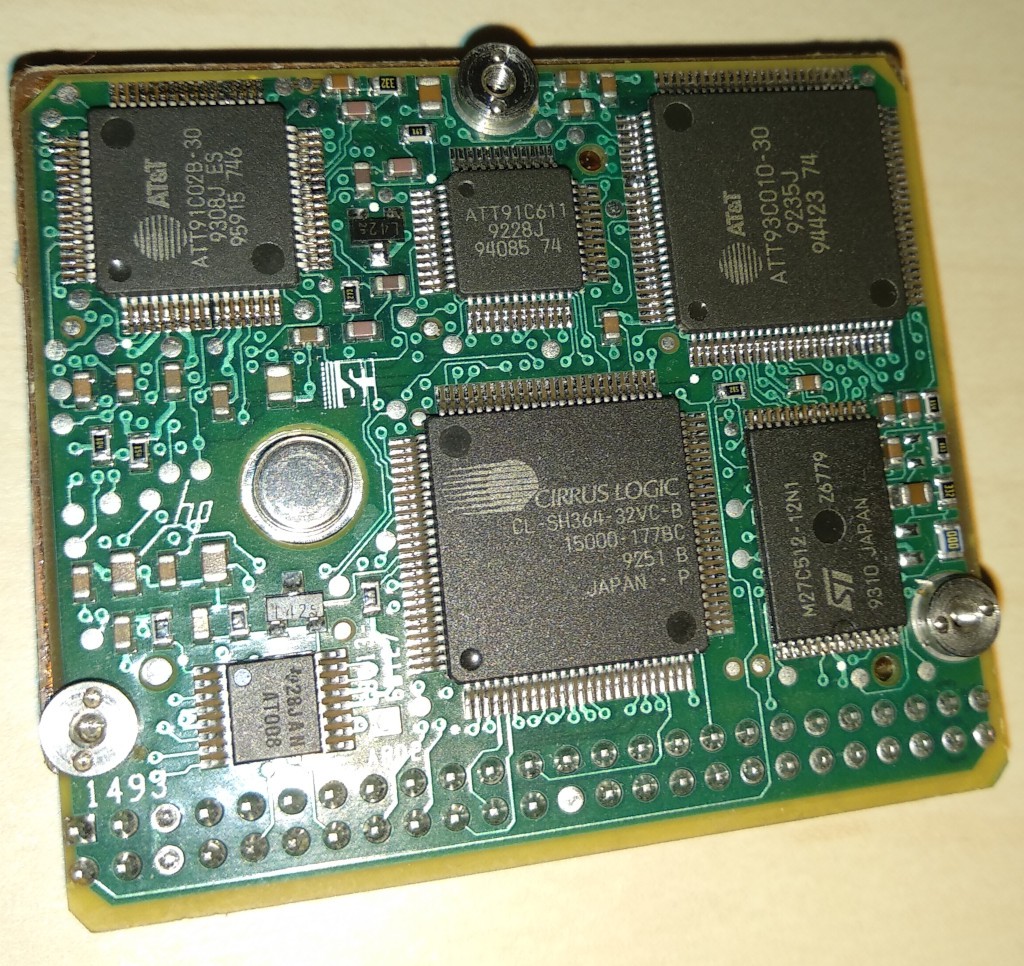
    Motherboard carry some components as mezzanine cards: CCFL inverter, keyboard+touchscreen controller, memory module and NIC card (optional). Phone line for modem are connected through the Cermetek's CH1817 module, secondary power are also generated by monolith module by Power Sensors Corp. PlanarPower(tm) PSD 015-3CC.


    HDD

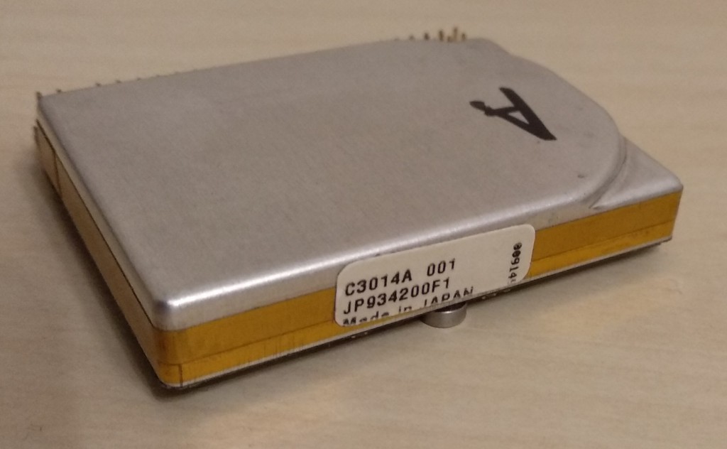
    DTR-1 has a 40Mb HP KittyHawk drive, some older machines may have 20Mb drive from the same series.

    While KittyHawk is not as famous as IBM's Microdrive, it is clearly an unique piece of art:

    I do not know other drives that can have the same physical size and connector placement and that makes very difficult to upgrade or replace HDD in DTR-1. But modern tech brings the alternate solution: there are cheap microSD/SD-to-IDE44 adapters that can fit the existing DTR-1 HDD compartment.

    They need to resolder connector to be at 90 degrees and cut PCB by ~2mm. I'll write a separate article about it later.

    KittyHawk drive supports PIO modes only and do not support LBA. Moreover, LBA is not supported by BIOS code, so there may be problems with implicit translations, for example Linux's LILO do not work as the CHS-LBA translation done by LILO do not match the addressing, that BIOS can support.
    Memory

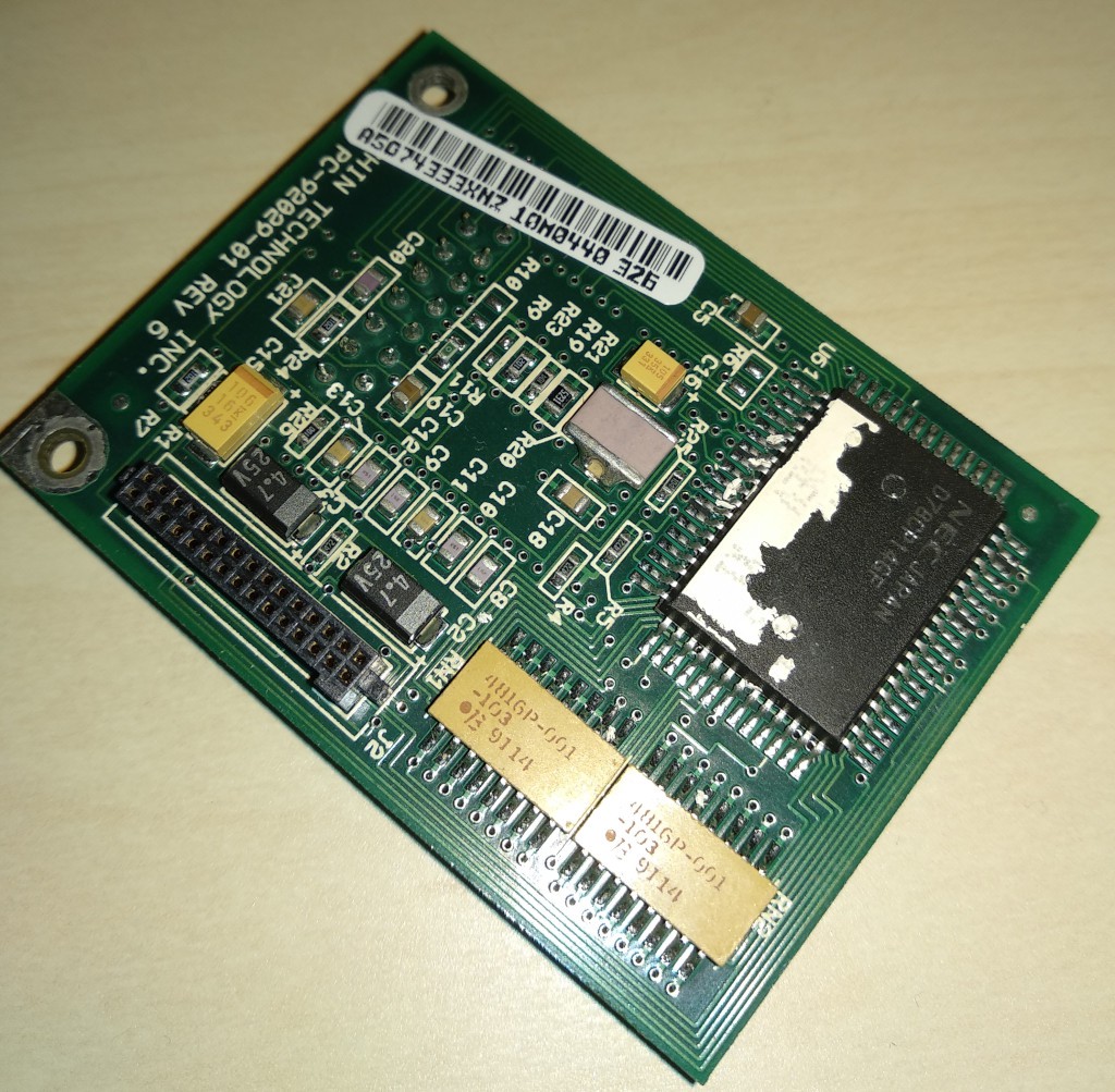
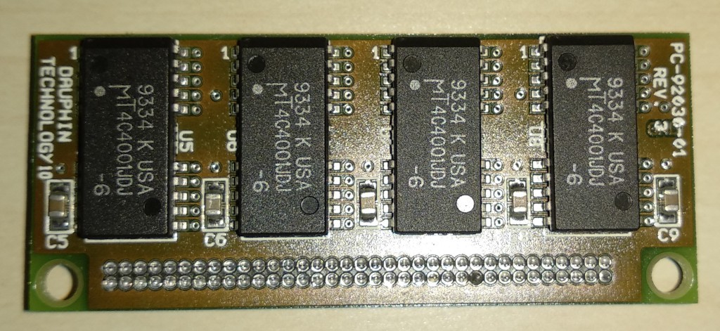
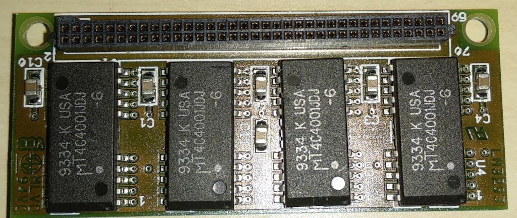
    Memory subsystem in DTR-1 consists from two parts: 2Mb (4 chips 1Mx4) soldered on the motherboard and single connector for attaching the proprietary memory module. Manufacturer produced 2Mb and 4Mb modules, single and double sided: 4 chips of 1Mx4 on the one side of module for 2Mb and 8 chips of 1M4 on both sides for 4Mb.

    In 2000 I've got the system with 2Mb single sided module and the lack of memory for Linux was the trigger to start  upgrading the DTR-1. Simplifying, memory subsystem consists from pairs of 30pin 1Mb SIMMS, that gathered into 16 bit data bus. It's enough for 386SX and Cx484slc systems. DTR-1 actually do not use 8bit 30pin SIMMS, but topology and electrical  connections between DRAM and memory controller are just the same as with SIMMs.

    2Mb of integrated memory is the first pair of SIMMS, second pair is routed to the back side of the module, third pair - to the front side.

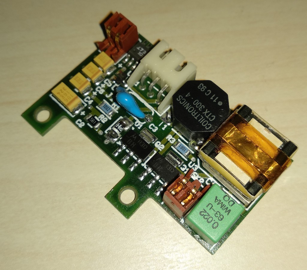
    CCFL

    High-voltage inverter for CCFL lamp are also implemented as the mezzanine card:

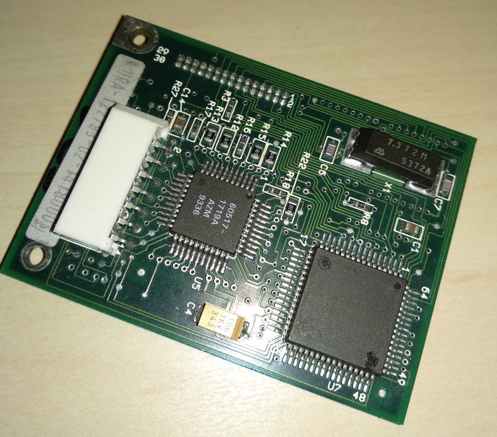
    KBC+Touchscreen

    KBC controller are implemented together with touchscreen controller. No 8042 MCUs are used in this board.
    Up to the current moment, it is the least rev.engineered board, except its connector.

    We'll investigate the motherboard more precisely in next articles.


  • DTR-1 Externals

    megov12/06/2020 at 13:08 0 comments

    External View.

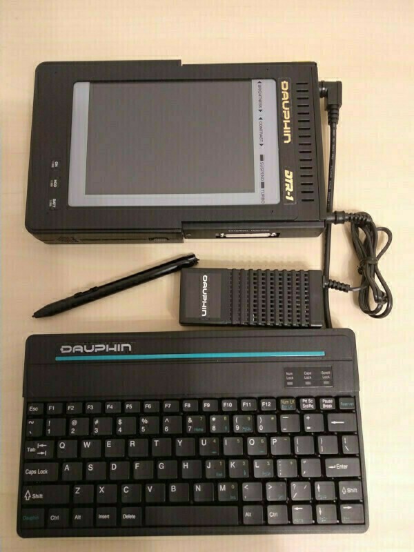
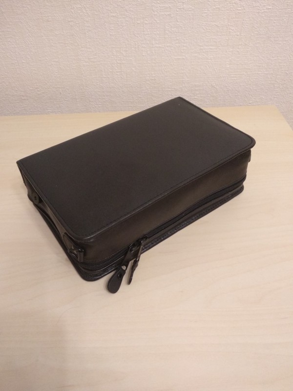
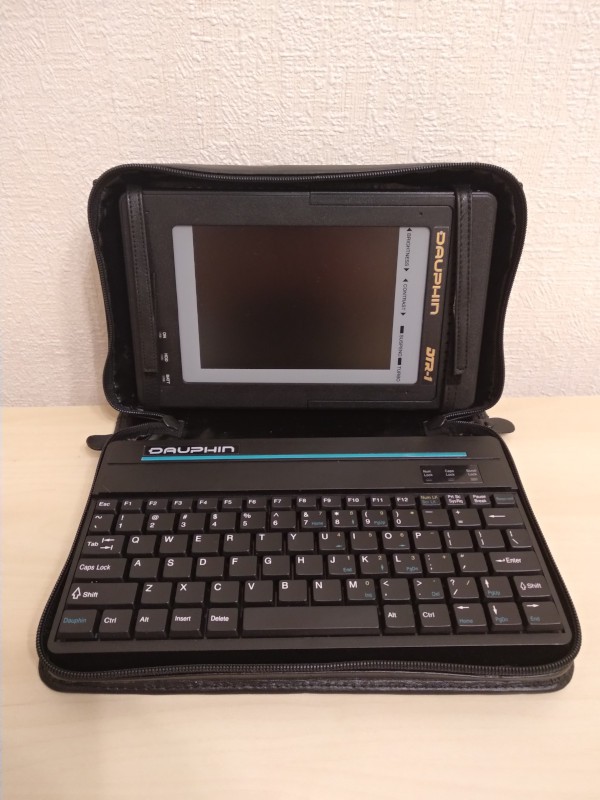
    Today there will be a lot of photos. When taken from the leather box, the system with PSU, keyboard and pen looks like that:

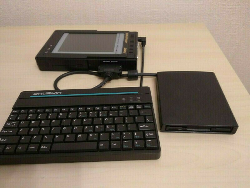
    Floppy do not fit well into the photo with PSU, so here is another one, now with FDD and without PSU:

    On the left side of the device there is 35mm wide battery compartment. It occupies the whole height of the system, that that's why left side has no connectors on it.

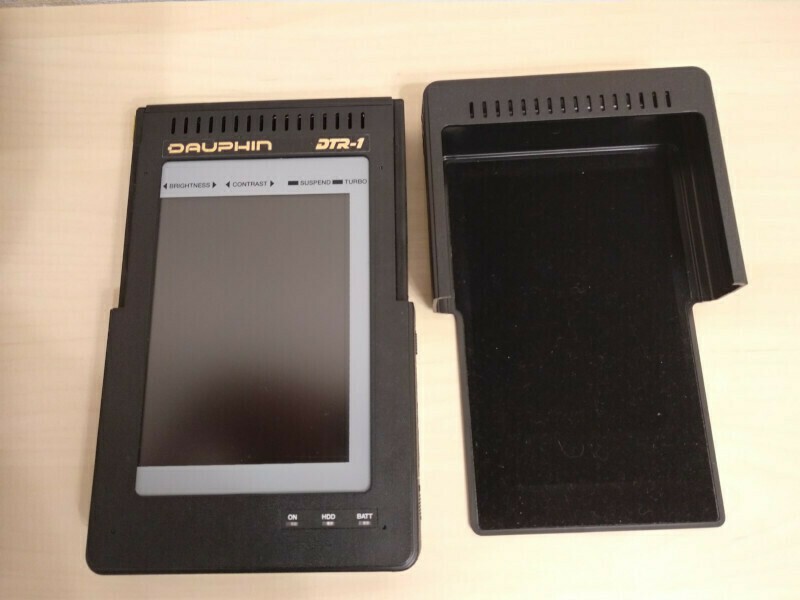
    Three LEDs indicating the power state of the system (ON, green), disk access (HDD, yellow) and battery state (BATT, red). ON LED blinks, when system goes into suspend mode.

    Battery cover and power slider switch located at the bottom side.

    Connectors.

    The system itself has connectors on the 3 of 4 sides.

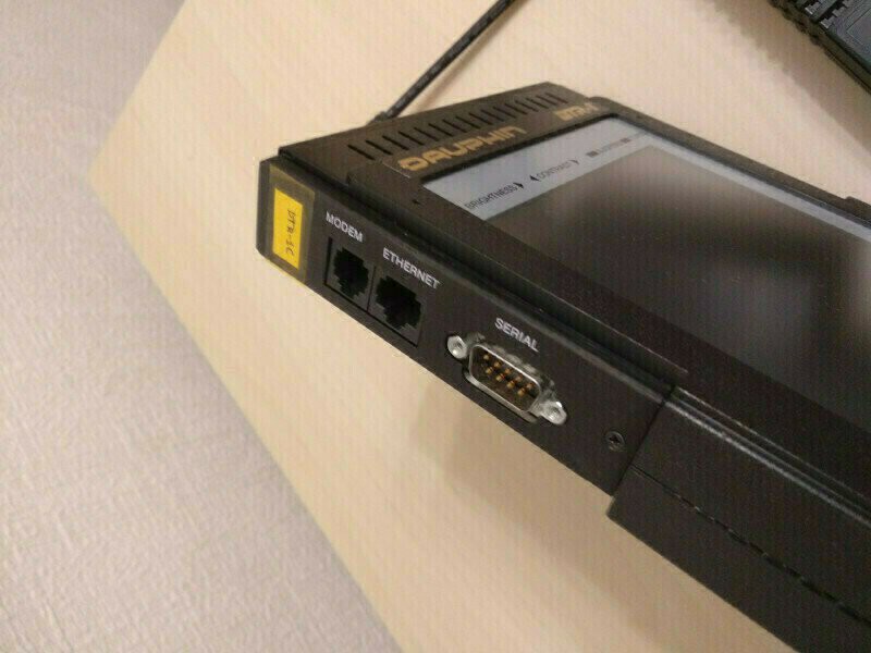
    Communication connectors gathered on the top side of the case. COM1 routed to a DB-9M RS-232 connector with standard pinout, but COM port internally shared with Rockwell modem. As the PIO chip implements 16450 UARTs, 38400 will be the maximal speed of serial port.

    Sharing COM1 between modem and connector means that only one device can be used at once. Switching are done by a pair of small DOS programs, they simply put different values into one of IO registers, possibly driving GPIO pin. I'll investigate it later. Modem connector is placed nearby and use a RJ11 (6P4C) phone jack.

    The last connector on the top side is RJ45 LAN 8P8C connector. Unfortunately, network speed is 10Mbit/s and connector only works when LAN mezzanine card are installed.

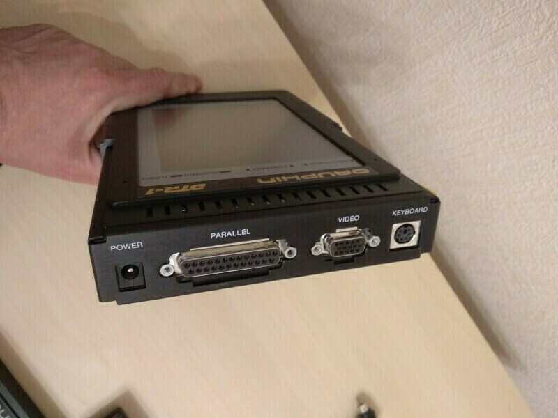
    Right side gathers peripheral and power connectors. Power supplied by 2.5mm barrel connector, parallel and VGA ports has standard connectors and pinouts. Keyboard attached via mini-DIN6 PS/2 connector with standard pinout.

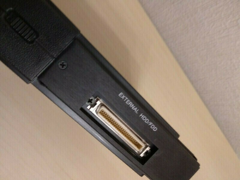
    Custom FDD/HDD connector located with battery cover and power switch on the bottom side. External HDD/FDD use high-density style 50pin connector, much like 68-pin connector used for external LVD SCSI devices. Some pins shared between FDD and HDD and I suppose, that connecting both at the same time may be impossible.
    HDD will be the slave device on the same primary controller. I do not own any DTR-1 HDD accessories, but will try to build adapter cable top 44Pin IDE if I can find HD50 plug for soldering.

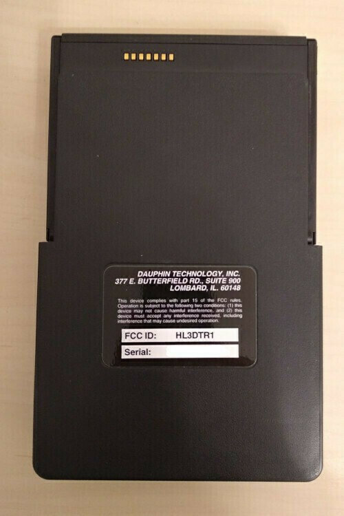
    Back side do not have any interesting things except the 7 gold plated contacts. There were rumors about  dockstation for the DTR-1. But the steel plate, that covers all connectors, the shape of the case and the 7 contacts makes me think, that some dock station maybe existed. While tracing the PCB I've found, that some of that contacts have a primary 12V power, so device can be powered (and charged) from the dockstation.

    The additional plastic cover hides all connectors except keyboard and makes the device looks like a real tablet computer. Not as thin as today's devices, but still...

    The design and location of connectors are not ideal, but they at least allow to use the tablet inside the leather case, while still connecting to power and network or phone line. Communication connectors are small, keyboard have 90-degree connector and PSU plus and cord just goes straight of the case on the lower right corner.

    Situation is slightly worse with LPT and COM connected, and worst with VGA, that conflicts with angled PS/2 keyboard connector and with FDD, that have large plug and short and hard cable.

    But all that usability stuff is unimportant. DTR-1 was a child of early 90x, when no microUSB, microHDMI, etc. yet exist.

    Keyboard.

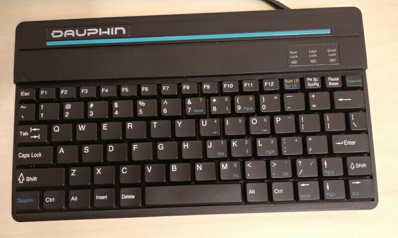
    DTR-1 have a simple membrane keyboard. It has 90-degree PS/2 connector and short cable, both designed to fit with DTR-1 into leather case.

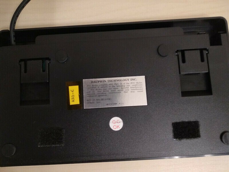
    On the back side there are two stands, that helps to angle keyboard slightly and two Velcro pieces, that helps to fix keyboard inside the case. Case has another two pieces of Velcro tape glued to the same places - cheap, but workable solution.

    Cable with connector may be moved to a compartment at the top of keyboard.

    Keys are thin...

    Read more »

  • Introduction

    megov12/05/2020 at 22:28 0 comments

      Once upon a time...

      There is a moment in the life of every man, when you stop and look into the past.
      The desire to turn back the spiral of time and to feel again the things of the youth is irresistible.
      Family man suddenly buys a Harley-Davidson and a leather jacket and starts to ride.

      And I'm not an exclusion.

      Twenty years ago my friend, who is a good electronic repairman, said me: "I have the thing you'll definitely like". And showed me the leather box:

      And I opened this Pandora's box...

      While in 2000 we do not suffer from the lack of computers, laptops and other electronics, this system captured me at a glance:

       - "How much do you want?"
       - "No, I'm not going to sale it."
       - "Nevermind. Say the amount!"
       - "Uhm.. Fifty bucks"
       - "Deal!"
      

      It was Dauphin DTR-1 - completely unknown beast for me at that time. Manufacturing date was about 1993 or 1994 and it was absolutely not impressive from performance point at 2000x. Who was interested in 486slc system with 4Mb of RAM and 40Mb HDD? It was quite used also: external battery was lost, internal battery was cut off, two pins of COM connector was broken and soldered by wires, pen has broken battery compartment. Power supply was lost, but providing 12V@3A was not a problem even twenty years ago ;)

      Many old systems died from NiCd battery leakage, but not this DTR-1 - my friend is a good specialist and cut off the internal battery before it leaks.

      Digging the Internet, I've found that DTR-1 may optionally have an external floppy, up to 6Mb RAM, and a network card. Mine has none and only 4Mb of RAM.

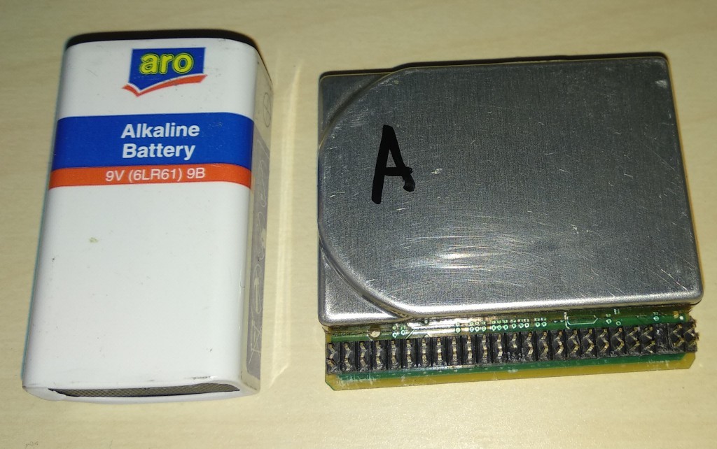
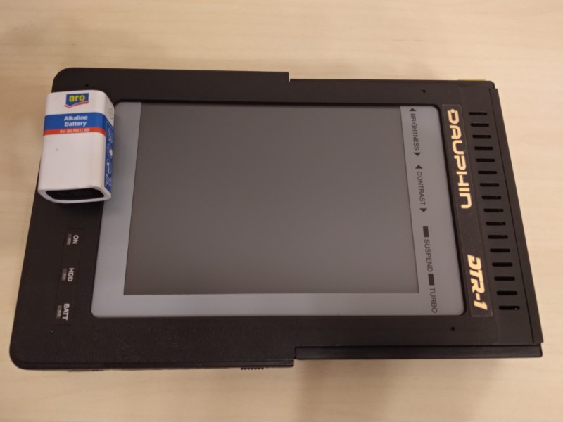
      System module have dimensions (approx) 142 x 225 x 35 mm. You can see it with 9V battery for comparison:

      I was a Linux adopter from the 1997 and was trying to setup Slackware 3.4. With 4Mb it may happen, but with 40Mb HDD, absence of NIC and floppy is was pretty impossible. It was the first challenge, that drives me to upgrade the system. As the internal HDD has standard 44pin IDE connector, it was possible to setup Slack on the "Big Brother" and run it later on DTR-1. But 40Mb was too few anyway.

      So, this project actually started twenty years ago.

      Back to the ground.

      Well, literature exercises is a beautiful thing, but let's go back to the hard technical ground.

      Machine was born in ~1993 and have the following specs:

    • CPU: Cyrix 486slc25
    • MEM: 2Mb onboard, +2Mb or +4Mb on the module. Up to 6Mb total.
    • HDD: IDE 44Pin, 20Mb or 40Mb HP KittyHawk drive
    • CHIPSET: Oak Technology OTI041/OTI042/OTI043 chipset
    • PIO: PC87311VF (2COM 16450, 1LPT, FDD)
    • VIDEO: OTI043 Vga Controller (LCD+VGA, up to 800x600, ??Kb videoram)
    • KB: PS/2 standard miniDIN6 port
    • MOUSE: Kurta pen tablet mouse (on COM2*)
    • MODEM: Internal Rockwell RC224ATF on COM1
    • NET: National DP83905 10Mbit UTP Mezzanine Card
    • FLOPPY: External FDD (slim 26 pin NEC 1137)
    • DRIVE: Possible second HDD on the same connector with External floppy
    • The main feature of the system is that it is Tablet PC from 1993. It has a detachable case, not like many laptops of that era. It has an inductive electronic pen, that can allow work in the tablet mode, with some software support, for example Windows for Pen Extension.

      Two COM ports were tied to Rockwell Modem (COM1) and Kurta Tablet Pen (COM2). I try to run Rockwell modem over the PSTN phone line, but the results was awful: modem do not support V.42 error correction. Sometimes I was able to connect Internet by provider's modem pool, but the connection was very unstable. The other thing is that PIO controller have only 16450 UART implementation, so no 57600 connection rate supported.

      NIC was (very) optional. I have none in 2000 so I try to use SLIP/PLIP in Linux to connect to outside. Last year I suddenly found these NICs on eBay and it became a trigger to start this project.

      Strangely, the system may have PS/2 mouse, but is was not implemented. I'll touch this issue when I'll discuss KBC.

      Dauphin DTR-1 was unsuccessful: it was created too early: neither hardware,...

    Read more »

View all 3 project logs

Enjoy this project?

Share

Discussions

blufeb95 wrote 09/26/2021 at 06:36 point

How well would a right angle 44pin Apacer DOM work in place of the HDD, they have a very small footprint, smaller than SD or CF adapters, but I don't know it the pinout is in the right orientation or mirrored, you might also have to remove the female connector and solder on a male connector, unless the footprint would still be short enough using a 44pin female to male adpater (2x22 2.0mm pitch pin header set)

  Are you sure? yes | no

Starhawk wrote 12/15/2020 at 00:18 point

That Cyrix 486 chip is going to hobble you, Cyrix chips can't do math. Almost as bad (not quite) as the IDT WinChip at the basis of everything VIA makes nowadays -- if you dabble in thin clients you know what I mean -- which is why VIA processors work equations like a 1940s adding machine on a Friday evening, with a dire need for lubricant and a thoroughly alcohol-soaked operator ;)

The WinChip did it by design, though -- it was specifically oriented towards parts of the computing market, which existed at the time (and largely no longer do) that just didn't need, or almost didn't need, floating-point operation support.

If the Cyrix is at all socketed, you should look for a replacement. I'd offer to send one, but I don't think I have a spare (I'd have to go look...) and the last time an American sent CPUs of that era to Russia it kind of made the news. (That was a Cold War spy joke.) Also, there is a **VERY** high chance that that 50pin external drive connector ("FDD/HDD connector") is actually just 50pin SCSI, the first generation stuff like you'd see in eg a compact Macintosh such as the Mac SE/30. It's certainly the right era!

I wonder how common these were in the States...? Almost certainly not at all, there were still hard feelings between us at that point :( There still are, really... a pity. We really should all learn to get along!

  Are you sure? yes | no

megov wrote 12/15/2020 at 02:14 point

No-no-no! Cyrix CAN do the math! Earlier Cyrix x87 FPUs was quite good performers.

I own 6x86-120 (aka M1) that actually works at 100Mhz FSB and it was near the P54C at 133Mhz. In generic integer math. Things were worse for floating point, when it was near Pentium 75. So I had quite fast Windows 95 but slow Quake at that time ;)

And as for CPU in Dauphin DTR-1, it used a Cyrix 486slc-25v - a 386sx class processor, but created from scratch by Cyrix engineers. It is almost pin-to-pin compatible with Intel 386SX, has QFP100 package and 1kb of L1 cache.

Of course. it performs more-or-less nearly as 486sx at the same speed: 16bit data bus inherited from 386SX slows it down on IO while 1k cache somewhat helps.

I will post an article about CPU in DTR-1 and its resoldering to TI 486slc2.

And for adding Cx87 FPU too!

As for FDD/IDE connector, I'm 110% sure that there is no SCSI at all. Just the same physical connector only. 40 lines IDE + 34 lines FDD are actually contains much less signals, many lines are ground, so it is possible to put both interfaces to the same 50 pin connector.

  Are you sure? yes | no

megov wrote 12/14/2020 at 22:56 point

HI! Pen is the pain ;)

I have two: bought 20ty years ago with the first DTR-1 and (suddenly) found with the second DTR-1 bought last year. Both had broken battery compartment. The case of first was broken completely and was reimplanted into pencil's case with USB-A cable to take power. The second one also was broken by me - I tried to fix a case, cracked at the top with thermo-shrinking tube and it smash the top of the case while shrinking under hot gun.

The overall pen subsystem will be investigated in future, of course. It will be not easy, as in addition to pen, there is an inductive plate at the backside on LCD and two chips on the keyboard controller mezzanine card, that tracks pen position and handle serial communications.

Troubles is that I've found no datasheets for chips and inductive backplate covered with foil and I can't disassemble it without fear to break.

  Are you sure? yes | no

Alexander wrote 12/12/2020 at 14:10 point

Cool! Will watch your progress of creating documentation. I own a dtr-1 too. It lacks the stylus and I was unsuccessful in finding a replacement. It would help to know how the original stylus worked, maybe then I could make one myself.

  Are you sure? yes | no

Similar Projects

Does this project spark your interest?

Become a member to follow this project and never miss any updates