Until now, the GameTank generated sound using discrete logic ICs to generate two square waves and a noise signal, as well as loop through short clips of PCM sample data that would be fed to a DAC to produce arbitrary waveforms. These four channels would be generated separately and then mixed together using digital potentiometers to control the volume of each channel.
This potentiometer was the DS1866+, and unfortunately it was abruptly discontinued in 2019. Most options for replacing its role in the soundcard design would have required not only an overhaul of the mixing scheme, but also an overhaul of the CPU's interface to the audio hardware.
So, I started by considering an approach where each channel is summed in the digital domain rather than analog. This would use a few adder ICs to combine all the channels and then feed them through a shared DAC. Given that most available adder ICs are 4-bit, I'd need six of them to combine the four channels.
This seemed like a bit much, so I then considered an approach where a single pair of 4-bit adders was used, the four channels would share an output bus with the adder's input, and each channel's output buffer would be activated in turn to add these values into an accumulation register which would then be loaded into the DAC.
Finally I realized this was becoming its own little discrete logic CPU design, which isn't actually my goal and would have made the soundcard huge. The only reason I haven't used any microcontrollers for subsystems on this project is that it "feels like cheating" to include little computers into my computer design that are individually more powerful than the whole.
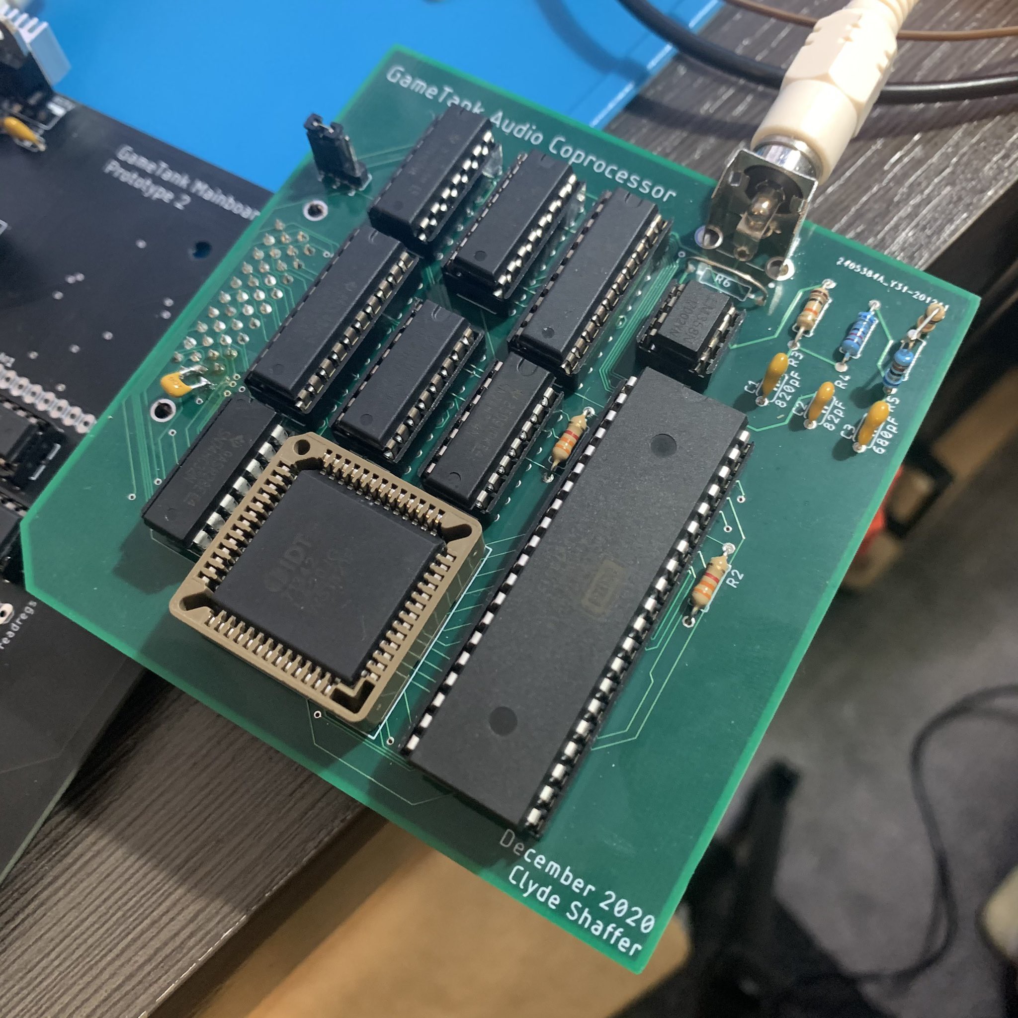
But what if the little computer-within-the-computer was equally as powerful? This seemed fine according to my completely arbitrary rubric, so I spun up a daughterboard design that simply used another 6502 to control a DAC.

The interface carried over from the old soundcard provides 7 memory-mapped selection signals, 4 kilobytes of memory access, and all four of the clock divisions used in the system. So it was relatively trivial to control the new Audio Coprocessor by loading programs into the dual-ported RAM and manipulating the RESET, READY, and NMI lines with the memory selection signals.
The design for this audio computer is actually pretty simple. The dual-ported RAM is wrapped around the whole 64k address space, while the DAC register is written on any write cycle while A15 is high. To prevent jitter on the audio sample rate, a 40103 8-bit down-counter is used to generate an interrupt that generates each audio sample. The samples sent to the DAC are double-buffered, meaning that every time the IRQ line strobes it copies the sample generated by the previous run of the interrupt handler. As long as the handler can complete in the time between samples, it doesn't matter precisely how long it takes to generate the final DAC value.
The jumper in the picture is for switching the coprocessor's clock between 3.5MHz and 7MHz. The system's main CPU runs at 3.5MHz due to the rather loose timing of the address decoding and the devices hanging off of the bus. I figured that the Audio Coprocessor could run a bit faster due to its simplicity, but I hadn't realized that it would even run fine at 14MHz. Not pictured is the bodge wire I added to let the audio system run at 14MHz, giving ample headroom for more complex audio synthesis routines.
Once I had determined that this new soundcard design was working, I wrote up a program for it that had similar capabilities to the original soundcard design. I'm not sure this technically qualifies as irony, but that code ended up being remarkably similar to what I had already written in C++ to generate audio in the GameTank Emulator. I'm not sure how many times in human history someone will replace a swath of C++ code with a call to a 6502 emulator performing the same computation.
To test out this device, I converted the music playing code from Cubicle Knight (the GameTank's flagship platforming game) to support the new interface as well as address four audio channels instead of two. Cubicle Knight only used two square wave channels for music, reserving the noise channel for sound effects and ignoring the PCM wavetable. The converted music player code uses the noise channel for percussion and utilizes the fourth channel for sine waves, in addition to the square wave instruments. For the song selection I went with the good ol' demoscene standby Bad Apple, itself a remix of a theme from the Touhou Project series of bullet hell games.
To encode the song I wrote a script in Node JS, which converts a MIDI file into a series of bytes that alternate between describing note length (in 60ths of a second) and note number. The script assumes that the MIDI file follows a certain rules and has a certain structure, so I had to painstakingly notate my own arrangement into a 4-track file. I also was forced to finally stop procrastinating on certain timing bugs in the conversion script, weren't noticeable in Cubicle Knight's soundtrack but became glaringly obvious after including a drummer in the ensemble.
The song runs at about three minutes, and uncompressed the song data weighs a "whopping" 8 kilobytes. Which is unfortunately the entirety of general-purpose RAM on the current motherboard design. To deal with this I borrowed some space on the video card, which has two 16k framebuffers and 32k of offscreen sprite memory. For the purpose of the video I chose to use the on-screen framebuffer to store the uncompressed song data on the top half of the screen, but it could just as easily be stored in sprite RAM.
Of course, my next goal will be to play not only the song data but also the animation that goes with it. The shadow art of the Bad Apple video reads well at low resolution, and compresses well being mostly monochrome. (Though the original does feature some grayscale). However, even when squeezed down to 128x96, converted into Run Length Encoding, and played at 15 frames/second, the frames of the video still add up to just under 2 megabytes. This dwarfs the size of the cartridges I currently use, which are essentially breakout boards for 8k EEPROM chips.
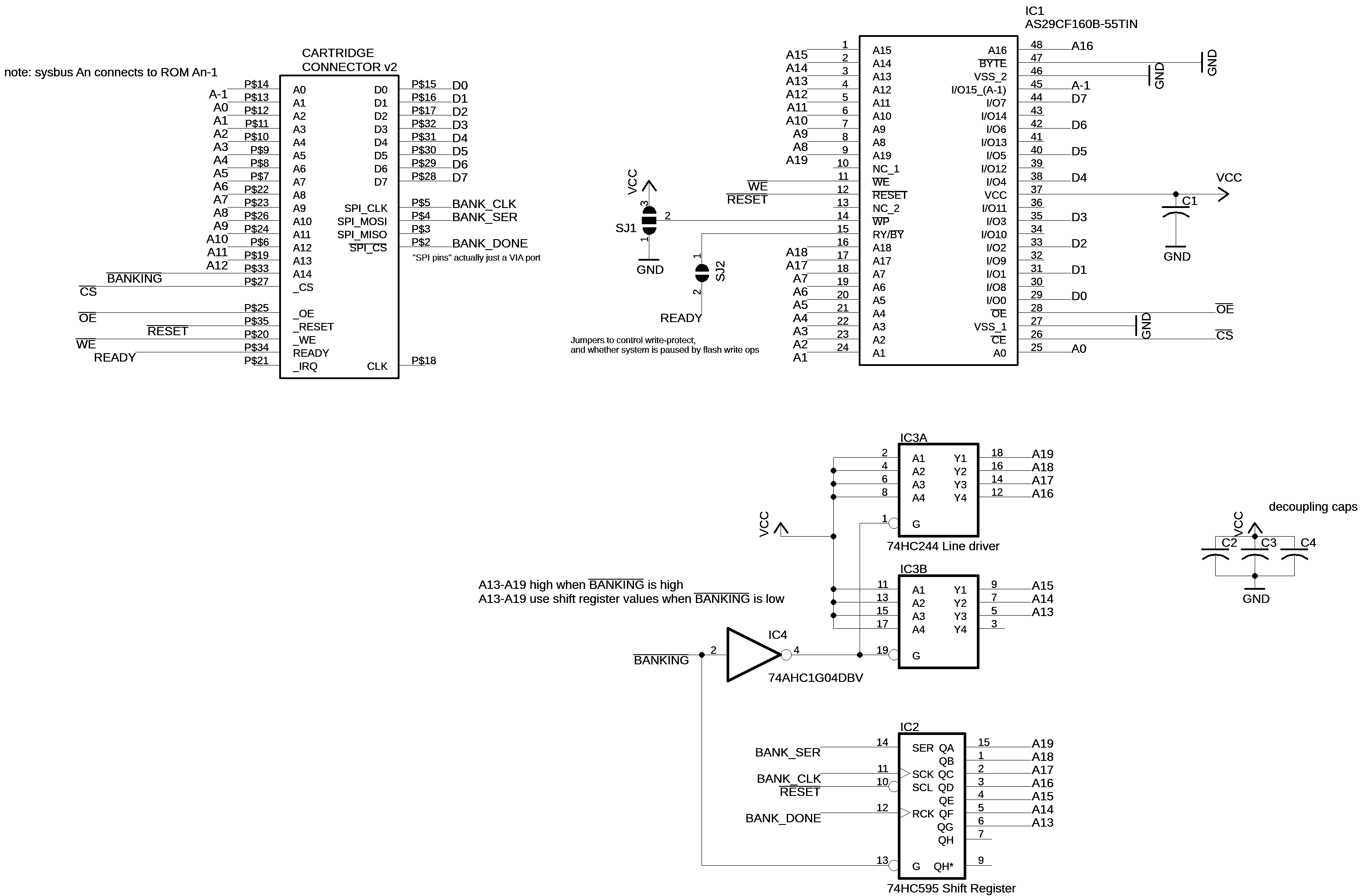
My next focus will be on prototyping cartridges that use parallel flash memory chips with a 2MB capacity. Since this is bigger than the 6502 can natively address, this will require a banking scheme. The prototype cartridge boards for which I am now awaiting delivery accomplish this by using a shift register to set the most significant address pin on the memory chip whenever A14 is low. The importance of that last qualification is that the CPU will always be able to access the interrupt vectors at 0xFFFA-FFFF and a program executing from the top 16k of memory will not be interrupted by a bank switch.

 Clyde Shaffer
Discussions
Become a Hackaday.io Member
Create an account to leave a comment. Already have an account? Log In.