Eliminating Resistors in the Balance Lead Mux:
I was able to remove the resistors used in BAT1's balance leads by simply connecting BAT1's balance leads to the balance lead mux if BAT2-BAT4 were not charging. Unfortunately, high currents could flow temporarily in the mux switches if they didn't disconnect properly before connecting another battery. This is getting complicated enough to employ a micro-controller.
Fixing Problems Caused By Balancing Currents:
I found a very bad issue with the cell balancing operation of the ToolktRC M6D charger. The charger is yanking so hard on the balance lead mux that it exceeds the 100mV threshold of the swap detector comparators. Here's a scope trace of the problem:
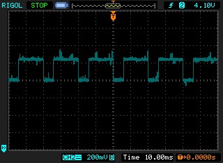
The charger applies current to the mux to balance each cell. It does this periodically and then turns off the current in order to measure the voltage across the cell to decide whether to continue applying balance current. In the M6D's case it performs this cycle every 20ms. The PFET RDSon of the balance lead mux is about 50mR at Vgs = 3.6V, so two of them in series is ~100mR. Therefore the balancing current used by the M6D is about 2.5A. This is a single battery connected to the charger -- it will be lower as batteries are connected and the mux resistance is decreased. I also measured the battery voltage while the balance current was applied -- there was no measurable voltage movement at the battery.
This is a big problem because the swap comparator disconnects the balance leads from the charger every time the voltage across the mux exceeds ~100mV. Therefore the cells don't receive any balance adjustment.
The SkyRC Q200 charger doesn't use such a large balance current. Here's what it looks like at the charger's balance leads:
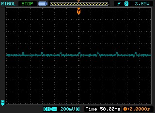
The balancing current causes less than 50mV of voltage across the mux switches. It also happens at a much slower rate.
Going to the Dark Side:
The only way that I could think of to solve this problem was to add a micro-controller -- a PIC 16F18323. This particular PIC is cheap at ~$1.00 in low quantities, comes in a 14-pin TSSOP package (which is relatively easy to hand solder), has a 10-bit ADC, and pretty low supply current even while running at a 1MHz system clock. And...I'm familiar with it. But several other PICs could be substituted into the circuit: 16F15223 or the 16F15323. The 16F15223 is the lowest cost of the bunch at $0.66, but its clock can't be set other than during a power on reset. (Even so, it still claims to draw less than 1mA @5V with a 1MHz clock.)
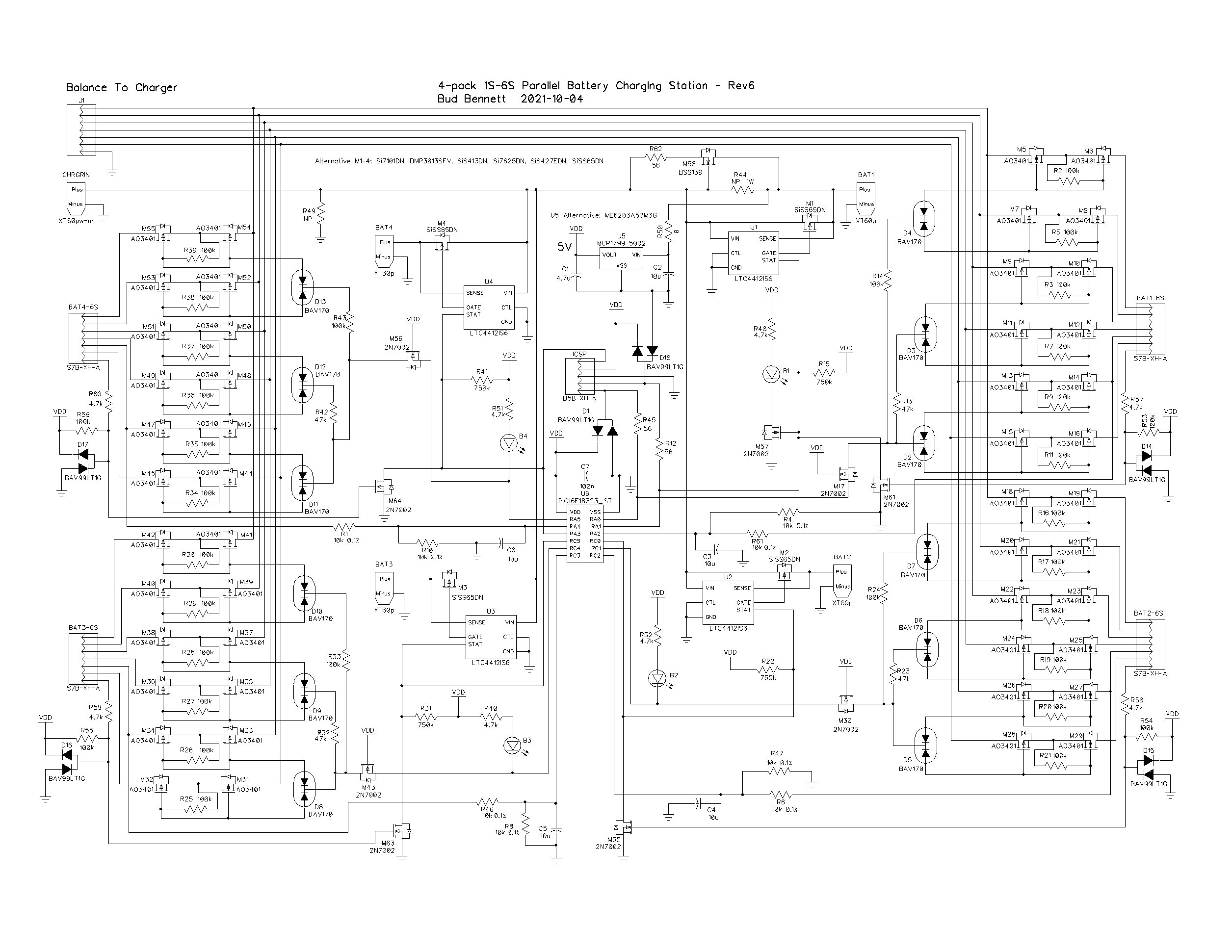
Adding the PIC removes the four swap comparators and a few other components to give some breathing room to the 500pin limit of the free Diptrace license. The PIC will use its internal 10-bit ADC to measure the battery voltages directly to determine if it is safe to connect the balance lead mux. It also will provide a break-before-make operation to the mux to make sure that no high currents flow between the batteries.
The 10-bit ADC has a resolution error of +/- 2.44mV. The resistor pair that divides the 2S voltage down to within the ADC's range have tolerances of 0.1%, which yields an error of +/- 3mV when the 2S voltage is 8.4V. That's about +/- 5mV around a 50mV detection threshold, or a 10% tolerance window. Of course, this is all subject to change, which is the beauty of using a PIC.
All of the PIC pins are used. The MCLR (master clear) input on pin 4 is disabled so it can be used as an input. Unfortunately when MCLR is configured this way the 5V programming option is not available, and MCLR has to be allowed to be taken to 9-10V (TBD) when programmed. This requires some judicious pin assignments for an In-Circuit-Serial-Programming (ICSP) interface to make it easier to make changes directly to the PIC without having to desolder it for re-programming. I've had ESD issues when programming PICs in the past so some diode protection was added to the clock and data inputs.
Flow Chart:
Here's my flow chart for programming the PIC:
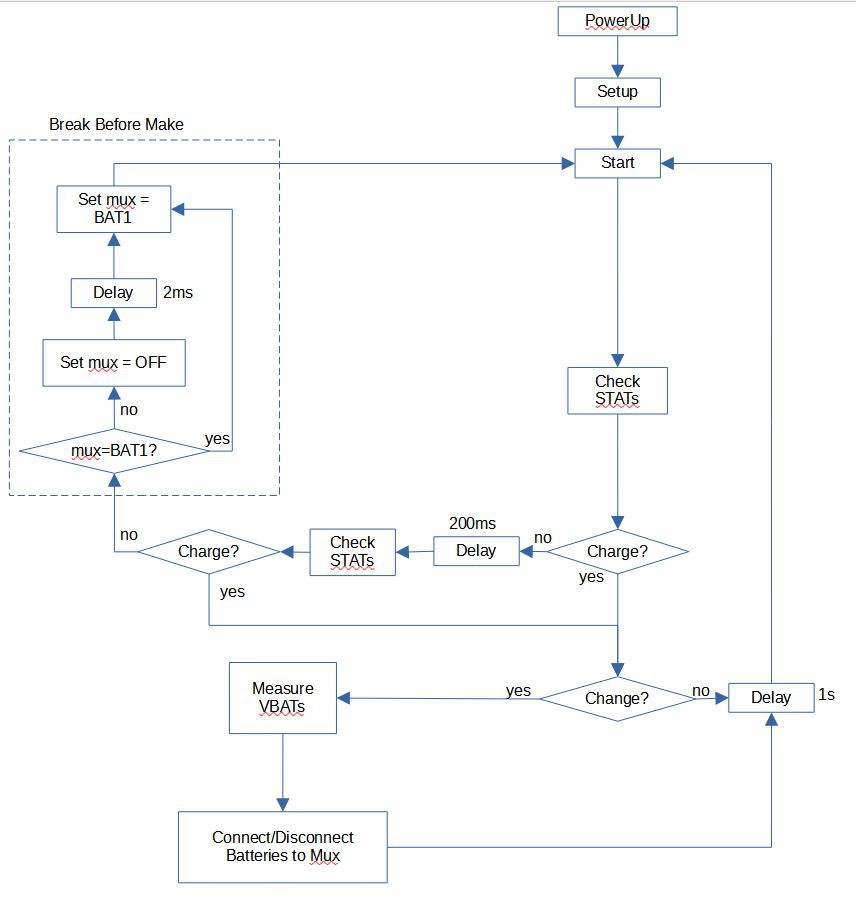
When the PIC first powers up it checks the four STAT pins of the LTC4412 ICs to see if any of them are charging. If none are charging then it connects BAT1's balance leads to the charger by performing a break-before-make action with the mux switches. If the system was charging and then stops, a second STAT check is performed after a short delay to make sure that the charger has really stopped charging instead of taking a quick break to make some measurements before continuing. It would be very bad if the parallel board disconnected balance leads before the charger terminated. I've seen the B# LEDs flash during charger operation, but haven't been able to catch it on a scope to figure out what is happening. This is just insurance.
Note that BAT1 is configured slightly differently than the other three. The B1 LED is controlled by the STAT output of U1. This allows BAT1 to be connected to the mux without indicating it by lighting up the B1 LED. B2-B4 LEDs light up whenever they are connected to the mux.
When a charge condition is detected it drops into the lower loop to service it. If a change in the number of batteries being charged is detected, the ADC measures all of the 2S cell voltages of the batteries and decides whether to connect of disconnect the balance leads from the charger. If there is no change in charging condition it waits 1 second before returning to the starting point.
The flow of decision process to connect/disconnect batteries to the balance lead mux is shown below:
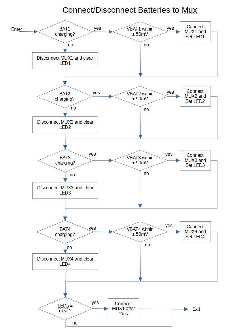
This isn't exactly what the PIC is doing, but it's close enough. There is a step, not shown, where if a battery is the first one to connect to the mux it must perform a break-before-make with the switches. In other cases, there is no need to worry about high currents flowing because the battery won't be connected if the voltage differences are too large. If all of the batteries are not charging then BAT1 is connected to the mux with break-before-make action.
 Bud Bennett
Discussions
Become a Hackaday.io Member
Create an account to leave a comment. Already have an account? Log In.