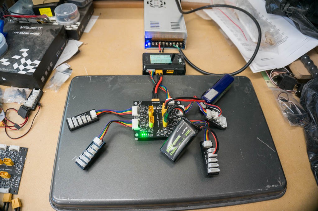
I just purchased a ToolkitRC M6D charger, and a 600W 24V power supply to go with it. With this setup I can charge four 4S Lipos at 10.8A (2.7A/battery) in each slot and use channel 2 for another four batteries. This new charger doesn't behave like my older SkyRC chargers. Changes had to be made to the parallel charger circuitry to get it to work with the new charger.

When I received the new charger it refused to charge anything. The calibration was so far off that it could not reconcile the voltage at the main plug with what it was measuring on the balance leads. I kept getting a balance voltage error. This was the case whether I was using the parallel charger board or directly plugging the battery into the charger. I thought that it might be a software problem, so I installed new firmware -- no dice.
Time to download the manual and read it...ugh. I found out that if you hold down the enter key while powering up the charger that it will enter a calibration mode. When I did this it was obvious that the charger calibration was way off. I think the main battery voltage measurement was in error by nearly 2V. It is amazing how many different voltages and parameters can be adjusted...but were not adjusted by the factory. After calibrating all of the voltages against my trusty DVM, the unit came alive and decided it was OK to charge a battery!
But it was not OK to charge using the parallel charger. The diode, D1, was causing the charger to exit with an error. I shorted D1's leads but still could not get the charger to pass its sanity check phase. The next step was to reduce the resistors R1, R4, R6, R8, R10 and R12 from 1k to 75R. After that the charger was happy and started the charge cycle. I did a quick back-of-the-napkin analysis and concluded that the 75R resistors would not cause any real problems, such as heat dissipation or significant battery discharge.
The only negative to making the above changes is that it is possible for an LED to light up as a battery is connected. This is a nuisance, but not a real problem since the user will probably start the charging cycle soon after installing the batteries. After the charge cycle has ended there are no LEDs that remain lit.
I charged a few batteries in parallel with mixed results. The matching of the cell voltages at end of charge was not very good. I dug out my 10x loupe and examined the connections on the PCB very carefully, and found several open connections in the balance lead muxes. After fixing the soldering errors on the two boards I intended to use with this new charger things proceeded as expected. It now regularly charges all of the cells to within +/-10mV across all of the batteries.
At this point in time I can't foresee making any more changes to the parallel station. It is working well for me. This project will be marked "Completed" sometime soon.
 Bud Bennett
Discussions
Become a Hackaday.io Member
Create an account to leave a comment. Already have an account? Log In.