-
Single-board computer initial design & PCB
12/31/2020 at 11:35 • 0 commentsWith a working cross-assembler and basic design, I am ready to design the board the preparation was intended for. The outline specifications are –
- 68B09E clocked at 8MHz, as that is the chip I got from Jameco.
- I had 32k EEPROM chips from another project, so that was a simple choice.
- I also had some 512k SRAM chips, so one of those could provide a ram-disk or some other paged memory.
- The 6850 used on the original board doesn’t have any Baud-rate generating circuitry so I decided to replace that with a 68681, which also adds a second serial interface.
- If I want to run Flex or other DOS then I need some kind of storage, and Compact Flash seems easy to interface.
- Most importantly, and the reason for the project title, I added a 6859 DES encryption chip. I found some NOS parts for a couple of Euros each and thought it would be interesting to experiment with them. They only do 56-bit DES but there is still some kind of export control on them.
The detail implementation turned-out to be quite straightforward, with a couple of extra constraints to fit the ‘small steps’ approach. I knew there was a good chance of making errors in the design so I wanted to be able to implement the original one within the new one, which meant including a 6850 for early testing. Only the address of the chip changes, so if the monitor runs then I know I have both RAM and EEPROM working. From there I can use the monitor to check each feature in turn.
Memory Map
The peripherals are all mapped to a 2k address space between $F000 and $F7FF. After reset the rest of the upper 32k is mapped to the EEPROM when reading, and RAM when writing, but the EEPROM can be disabled to give 62k of RAM. The intention is that code in the EEPROM can be copied to RAM at the same address then the processor switches to RAM-only without any other functional change.
An extra twist is that a 4k segment between $E000 and $EFFF can be mapped to any 4k segment of RAM by writing to a single register.
There are enough complexities here to be a challenge to debug so I was reliant on the monitor and serial interface to get me started.
Schematic
This is the design created, that I was hoping was mostly functional
PCB
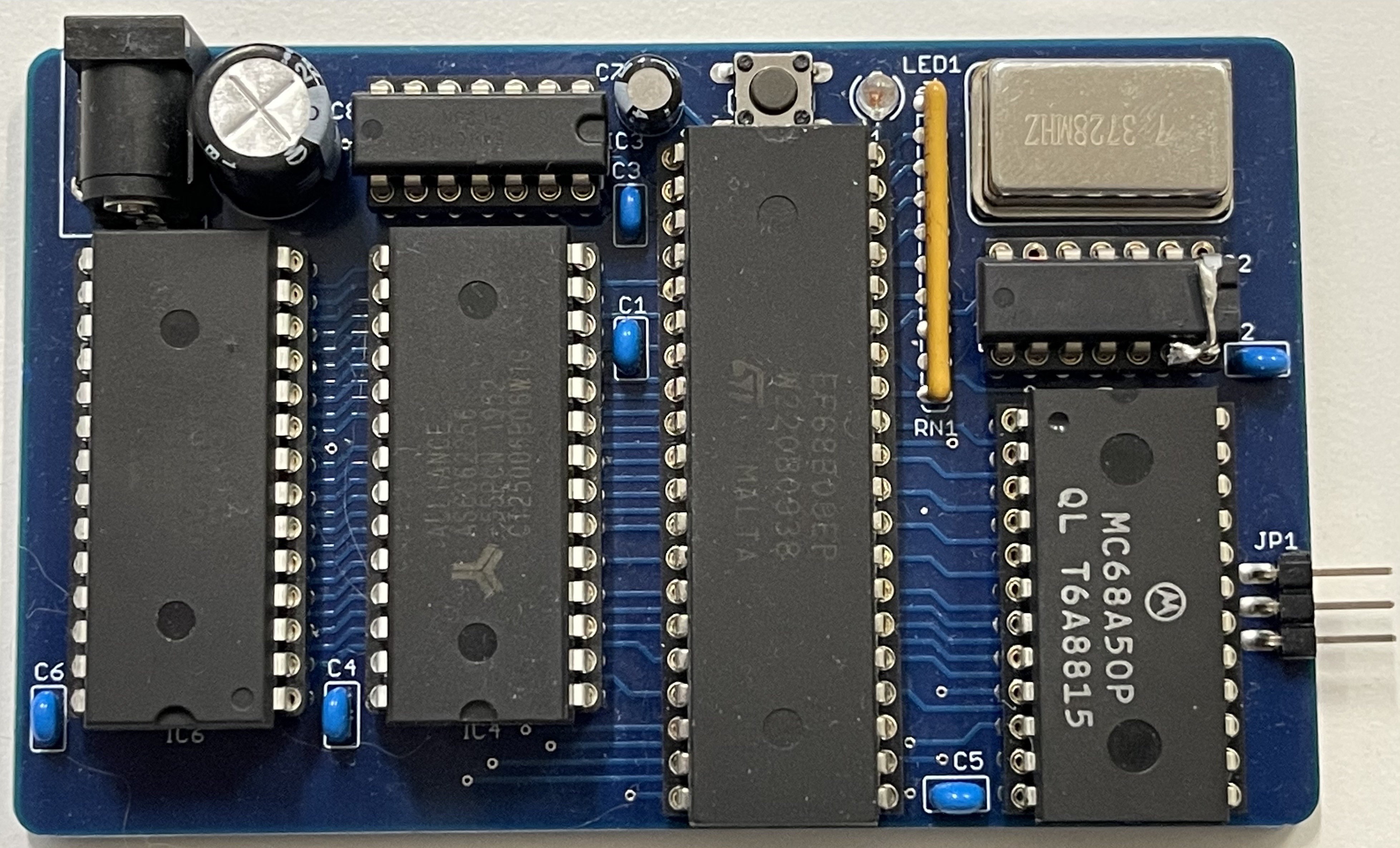
This is the PCB I received, before I assembled it
![]()
-
A09 on OSX
12/24/2020 at 14:35 • 3 commentsI looked around for 6809 assemblers for OSX, and there were three main options; A09, AS9 and lwtools. lwtools was a bit more 'serious' than I was looking for and AS9 was quite complicated to get into a form Xcode could compile, so A09 was what I chose. It compiled without problem but generated lots of errors when used, so clearly something wasn't quite right. The comments at the start of the code are quite explicit in the expectations of int and long bit-widths, which the compiler on my Mac didn't satisfy. Converting ints to int_16t and similar for longs the code worked and I could assemble Assist09, program an EEPROM and run it on my simple PCB.
There is an error in the check-sum generation for the s-records, but that can wait for another day. The updated code is here
https://github.com/valgamaa/A09-cross-assembler
and I can now progress to my full design safe in the knowledge that I have a working version of Assist09 that I can modify for the new board to bring it to life.
-
Little Steps
12/17/2020 at 13:35 • 0 commentsThe problem with getting a computer board working is that both the hardware and software need to be working correctly. If both are new then chances are neither works, so how to fix them?
In my case I decided to solve the problem in little steps. I found a blog by Jeff Tranter (http://jefftranter.blogspot.com/2019/01/a-6809-single-board-computer.html) where he had a simple design and functional software. Perfect! I could take the design, make my own PCB and the software on his git page to verify my version, then use the working hardware to verify my cross-assembler. With both of these tested I can make a 'real' design, safe in the knowledge I could debug it with known-working software.
![]()
As you can see, my cautious strategy paid-off. When there was no output from the serial port I knew that the fault was on my board, and a few minutes with a 'scope showed there was no clock signal. The 74HC74 CLR inputs were tied low rather than high.
Still no activity. A couple more minutes and I could see that E and Q had been swapped. Remove pin 6 and put a link between Pin 5 and 6 on the PCB and there was activity on the serial port. Success, I had the Assist09 prompt on my terminal emulator.
I now have a functioning platform to verify my development tools with, and verified footprints for a more complex design, so while it's disappointing I made a couple of simple errors they justify the 'small steps' approach.
I will link a GitHub page later to contain all the files as I proceed.

