 ogdento
The Amrel LPS-301 supply is a programmable 30V/2A unit that has a front-panel keypad and an isolated serial interface for computer control. The six-keys on the keypad set voltage/current values and enable/disable the output... and I don't love it. It really needs a knob! The LCD on my unit was bad so while I had it all apart to replace the display I figured I'd try to improve the controls.
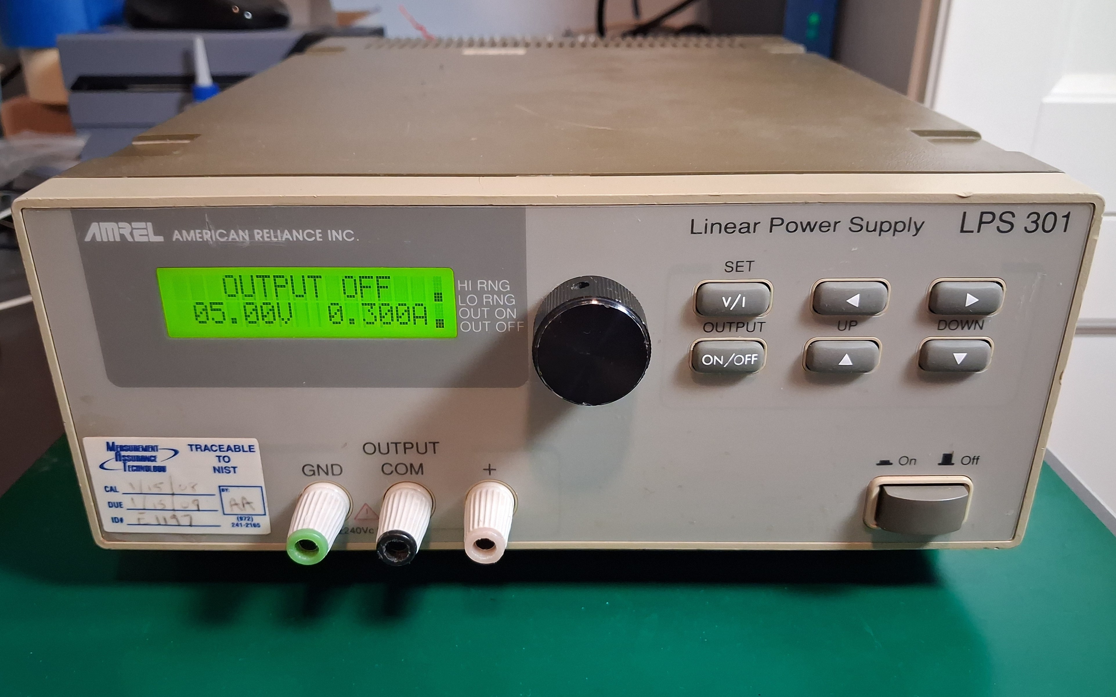
Here's a shot of the cumbersome-to-use front panel:
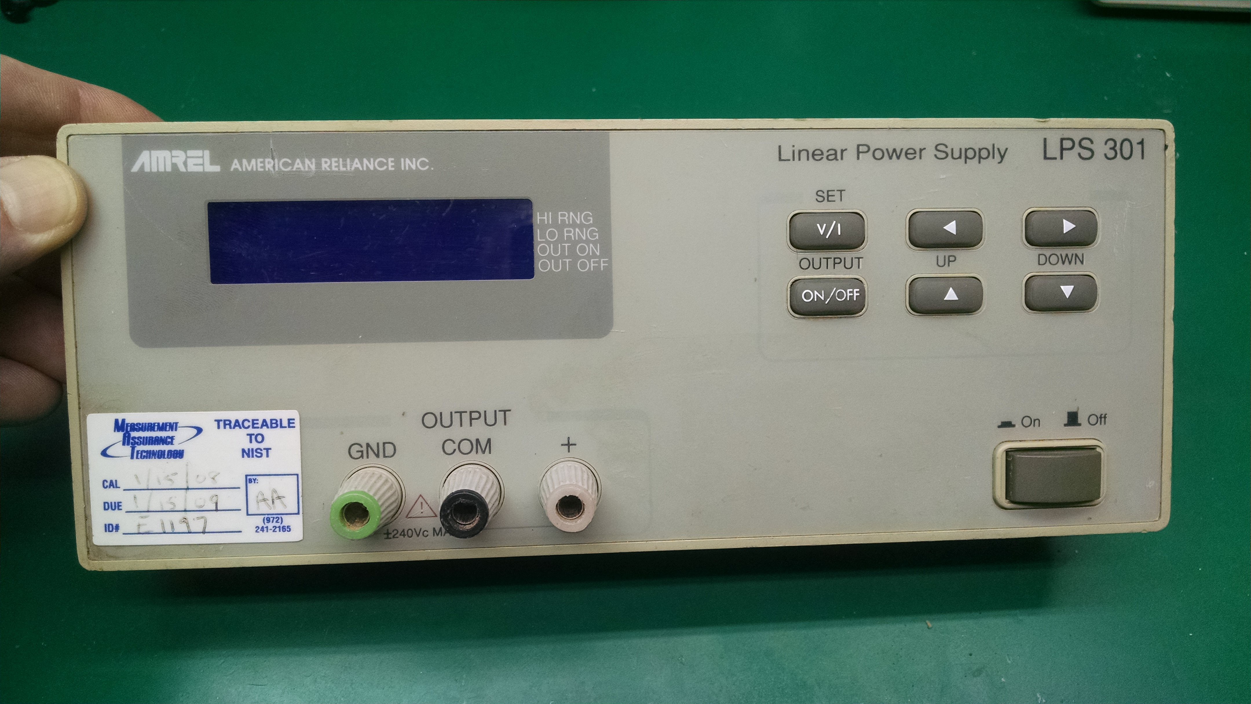
Incidentally, it looks like this front panel - and the mainboard inside it - is used for the other power supplies in the same product family. There's a dual channel supply, and a supply with a fixed 5-volt output that share many parts.
CURRENT BEHAVIOR:
Entering a voltage value with the Amrel keypad requires pressing the "v/i" key to select voltage, then the "up/down" keys to set the 0-9 value for the first of five digits, then the "right" key to select the next digit, the "up/down" keys to set that digit, the "right" key again to select the next - agh!... and repeating this for each remaining digit. The power supply changes to the new voltage and exits the v/i mode after setting the last digit and hitting the "right" key a final time. At this point the "left/right" and "up/down" keys can change any digit of the set voltage.
Once you start setting a voltage or current you have go through all five digits to get out of that mode. It would be nice if I could just set the first digit or two and activate it without pressing the "right" key four more times.
PROPOSED BEHAVIOR:
I'd like to add a single encoder with a pushbutton to perform the same voltage/current set operations that the keypad handles. I also want to be able to enable/disable the output with the encoder button and I want the option to exit voltage/current set mode without setting every single digit. I whipped up a rough diagram to show how it would work:
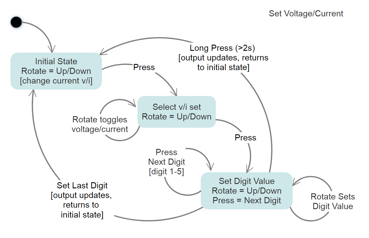
Rotating the encoder simply alters any voltage (or current) that is currently active. A button press enters the voltage/current "set mode" where subsequent rotation toggles between "voltage" or "current". Another button press moves to the first digit - just like using the keypad "right" key - and rotating selects the value. Yet another button press moves to the next digit, rotation selects that value... repeat for all remaining digits. After setting all digits the final button press changes the power supply to the new voltage. If you start setting a voltage and do a long press - or do nothing for 3 seconds - whatever value you've got so far is kept and the voltage/current set mode exits (a "right" key is sent for any remaining digits).
HARDWARE IMPLEMENTATION:
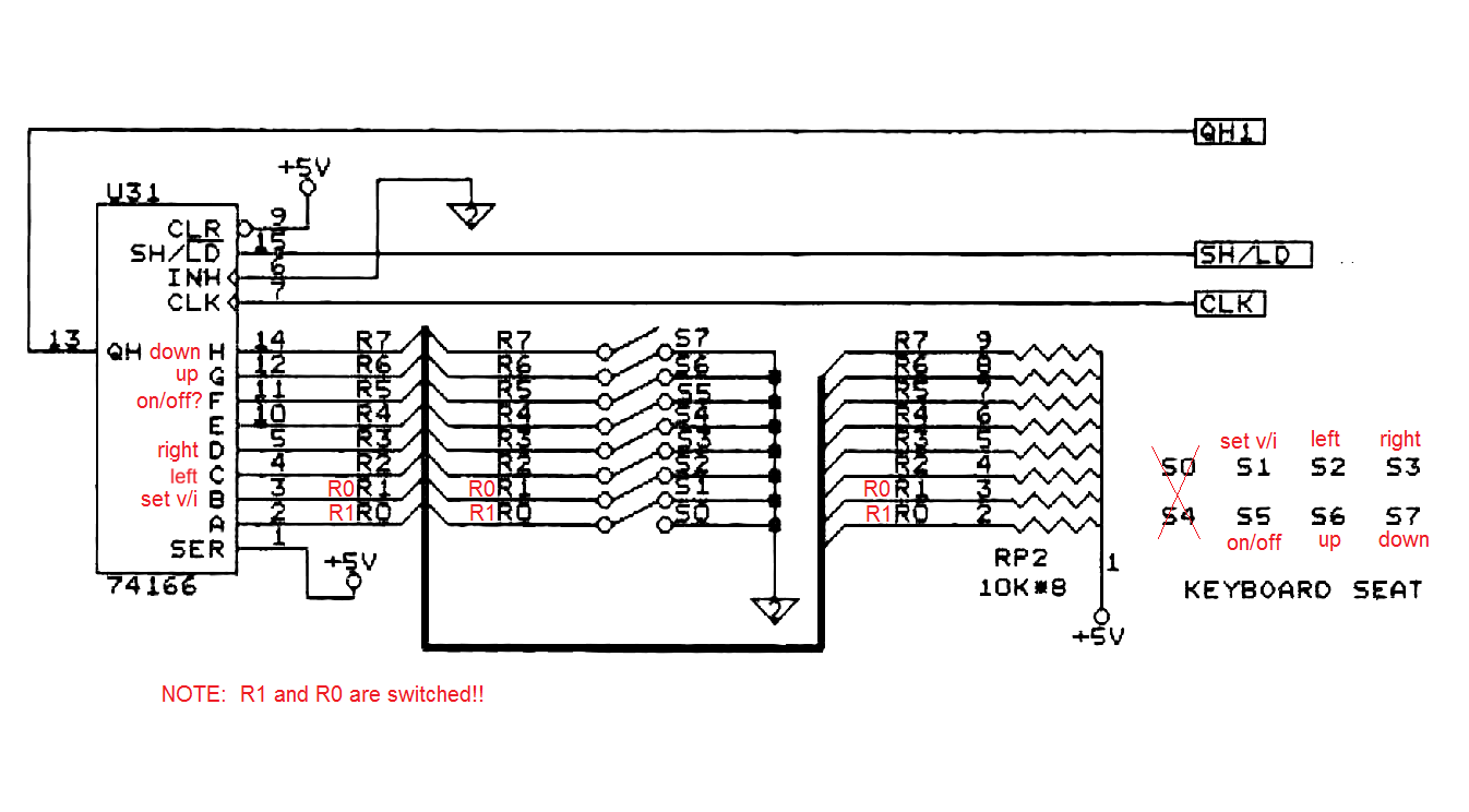
I initially thought I'd use the encoder and microcontroller to send commands over the existing serial interface to set voltage/current but I figured there may be some lag, and I didn't want to tie up the interface. I then considered talking directly to the onboard 80c31 controller so I started checking out the schematics from the service manual. I noticed that each key has it's own active-low signal line and is connected to a 74166 shift register with an external pull-up... I realized that by using a buffer chip with hi-z/open-collector outputs I could manipulate the keypad signals directly, without having to interface with the 80c31 or modify the board at all
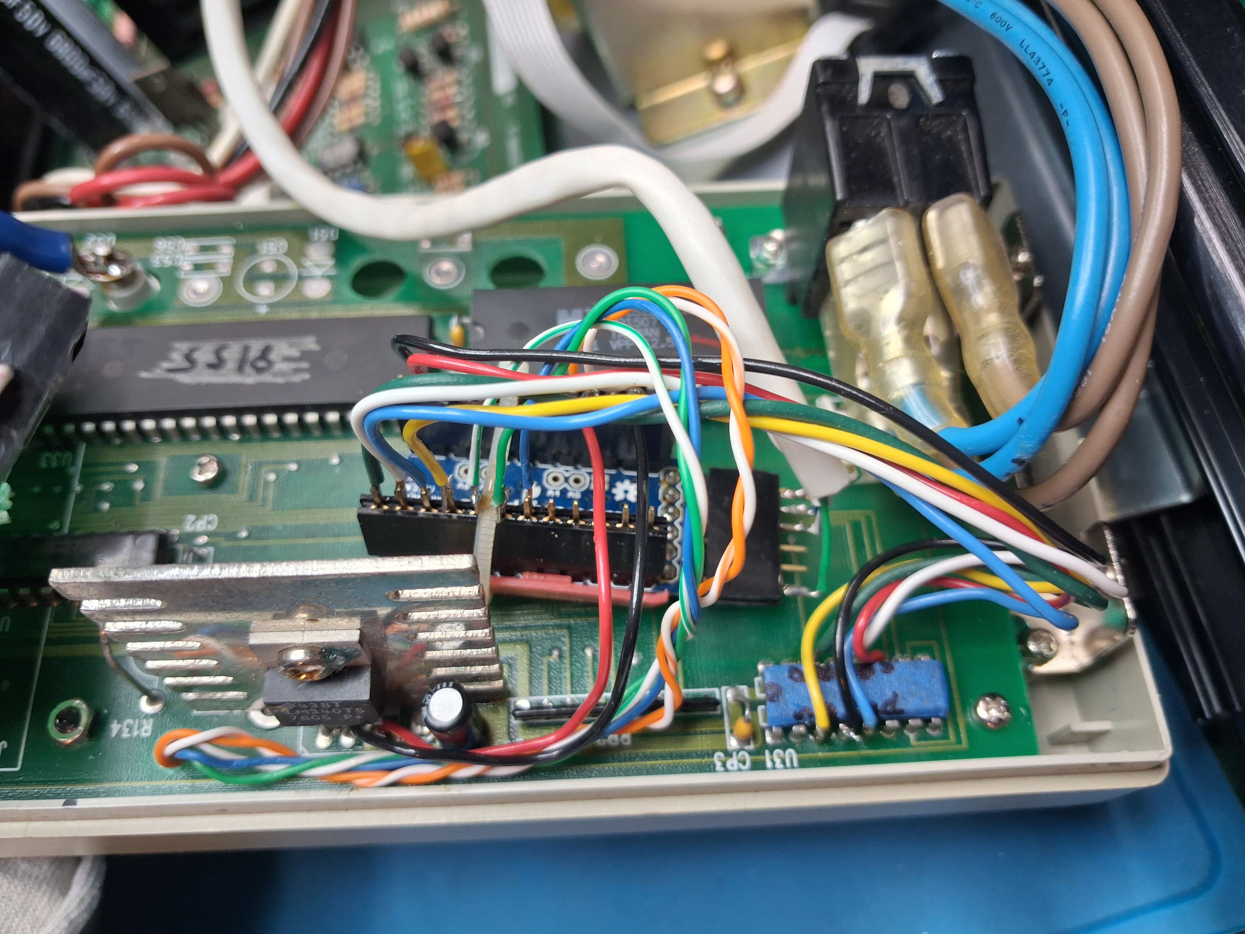
I had some 3-state buffers, an HW-040 encoder breakout board, and various micros lying around - but decided to eliminate the buffer chip and emulate an open-collector output in software, using an Arduino. I connected up the encoder, whipped up sketch, soldered a few wires onto the appropriate 74166 pins and... nothing. The Arduino was generating pulses based on my encoder inputs, but they were much too short and the power supply couldn't detect them. I increased the pulses to 50ms and it worked!
In the final implementation I didn't use the HW-040 encoder, mostly because I didn't know how reliable it would be AND it didn't have threads to mount to the power supply face. I used a Bourns pec11 from Mouser (pec11r-4215f-s0024) and used a small piece of proto-board to build the noise filter circuit from the datasheet. I had to keep it small so I could mount it in the space between the front panel and the main control board.
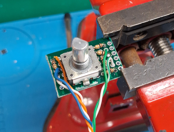
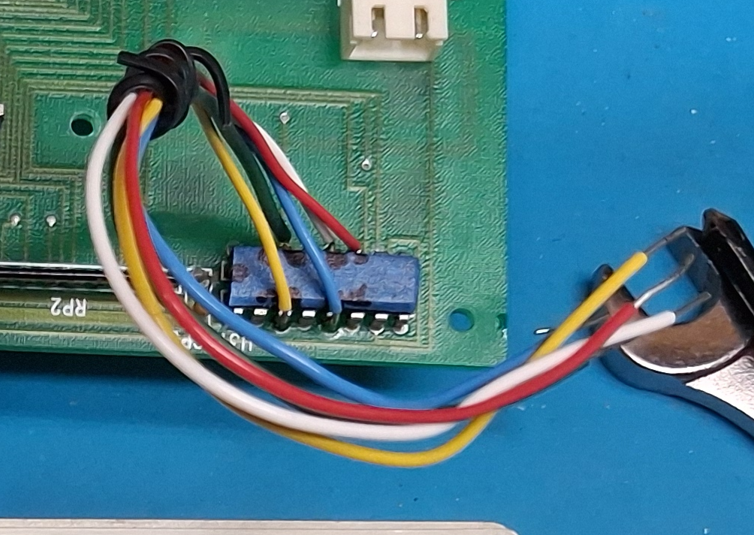
Here's the encoder mounted to the backside of the front panel board... the mounting posts are used to mount the main pc-board, and when I got this unit there was a post that had broken off - conveniently I used the corresponding hole in the main pc-board to re-route my wires through to the other side of the board.
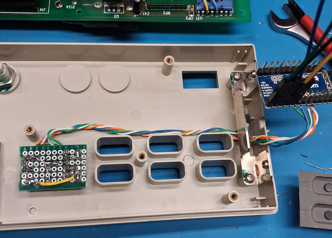
Here's a view of the original front panel board reinstalled with the Arduino wired in. I routed the encoder wires up through a hole from a broken post - I had to enlarge the hole slightly. I used a small red plastic scrap as a sort of "C" channel clip to hold the Arduino, and then I zip-tied it in so it wouldn't move. I soldered a black wire - for the LEFT keypad signal - to the 74166, and used a scrap of cat-3 cable to bring the Arduino programming pins to a connector on the back panel.
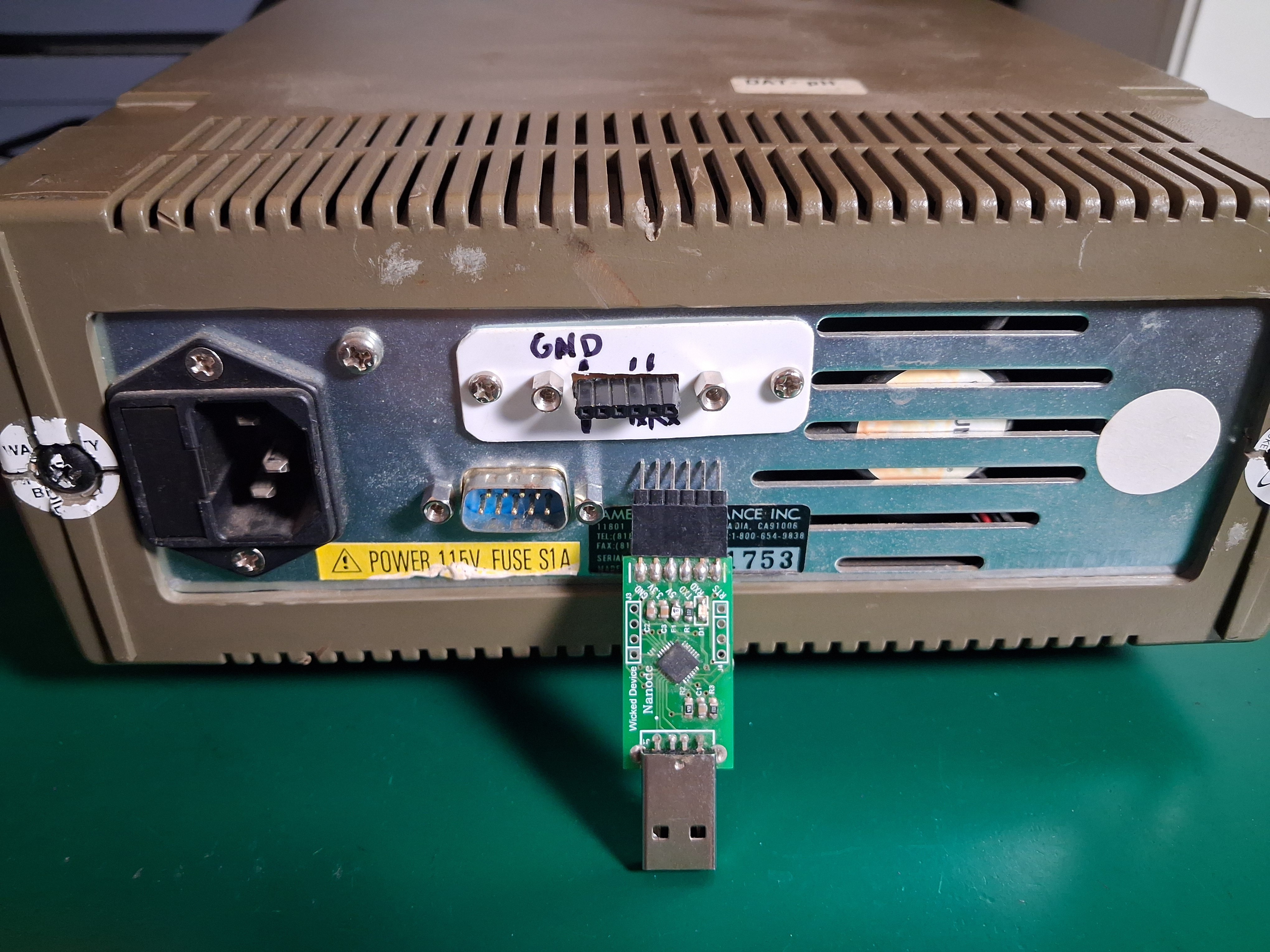
The programming connector was added to a chassis opening above the DB9 serial connector. The Arduino gets power from the regulator on the front panel board so since I did not connect Vcc on the programming header, the power supply must be turned on to program the Arduino.
Finally, this is the power supply with the encoder installed. I just used a knob from the parts bin for now, but I want to track down a gray knob that matches the device better. See the files section for a short video demonstration.
ARDUINO CODE:
The Arduino sketch is available in this project as a downloadable file, or as copyable code in the instructions section (it's not up on github yet!). It's fairly straightforward in that it just runs a main loop that checks some flags and counters that are set by a timer interrupt, encoder button presses, and encoder rotation. Timer0 interrupts once per millisecond - in the middle of the count so as to not disturb it's regular duties - and increments various counters.
The encoder button uses an external interrupt to detect a falling edge and "debounce" the button. It doesn't do the traditional time-based debounce but instead relies on disconnecting the external interrupt after a "button-down" and then resetting it on a "button-up"... which does a pretty good job. Once a button-down occurs, a button press timer starts counting - and stops when the button is up - so I can determine whether a short or long press has occurred.
I noticed an occasional short press immediately following the button-up of a long press... I figured it was either switch noise or an interrupt flag that didn't get cleared properly, but it was simple to code around it since I keep track of the duration that the button is down.
There's also a "timeout" timer to detect when there's been no activity after beginning a voltage or current set operation... it sort of operates like a watch dog timer in that any activity on the encoder needs to clear it for it to work correctly. In retrospect, I probably could have persuaded the actual watch dog timer to do this.
The encoder rotation code was pulled from a ten year old Adafruit example (see links for this project) and works really well. The code detects which of the A or B signals happens first and sets a variable that indicates whether the encoder has rotated, and in which direction (+1 for CW and -1 for CCW). Then I send a "right" or "left" key-press - or do nothing - depending on if and how the encoder rotated.
Key-presses are emulated with a routine that generates a low pulse of approximately 50ms on the appropriate keypad signal line. Concurrent key presses are not allowed, and after a key press pulse completes there's a "padding" time that must elapse before another pulse can be sent... this prevents the Arduino from sending pulses that are so close together that the Amrel can't detect them.
I also added some debug code that is enabled by uncommenting a pair of #define statements. There's a "debug" define that adds in some code to output serial data to the Arduino monitor. To use it I disconnect from the Amrel and change the pin definition on the arduino to input_pullup since I've no longer got the Amrel's pullups. There's also a "debug_pulse" define that causes a 50ms square wave to be output on the debug pin... I added it while debugging my non-working key press pulses and it helped me see they were too short.
OTHER CONSIDERATIONS:
I originally planned to mock this up with an Arduino and then re-write a more optimized version for a pic, but the Arduino sketch works well enough so I'm just going to keep it. The Arduino taps into an existing 7805 on the Amrel's front panel and it draws about 15mA... I don't think that's going to be an issue but I should also put the Arduino to sleep when not in use and wake it on a button press or encoder rotation.
I noticed some odd behavior with the UI if you use the encoder and the keypad at the same time... I wouldn't normally do this, but you might so I should make some accommodation in the design: A "keypad pressed" input signal, tied to INT0, will trigger an interrupt any time a keypad button is pressed. The interrupt routine will determine which key was pressed and make the appropriate adjustments such as updating any digit counts, or enabling/disabling the output, etc. The "keypad pressed" signal will be generated by a logic AND of the keypad signals I care about (left, right, vi, onoff) and will give me a low output if anything is pressed - remember they are active low. I'll also need to configure an input to capture the LEFT keypad button ("C" on the 74166). Not sure when I'll get to it, but I've routed the Arduino programming pins to the back of the power supply so I can make such updates.
Lastly, I was not at all careful to limit the amount of memory I used for my flags and timers so there's definitely room for optimization - especially in how many different counters I'm using... it could probably be changed to use just one.