For the original Think-a-Tron, I'm assuming that the game play went something like this:
- Someone reads the question from a card.
- Both players verbally declare what they think is the correct answer (A, B, C, T, or F).
- The card is inserted into Think-a-Tron, which is "activated" and reveals the correct answer.
- Players with the correct declared answer manually update their score counters.
- Repeat.
Now I'm assuming this because I have not been able to find a copy of the Instruction sheet that shipped in the box. If anyone out there has this sheet I would be eternally grateful for a copy.
At any rate Think-a-Tron 2020 will work a little differently:
- Someone reads the question from a card.
- Both players lock their answers into Think-a-Tron 2020.
- The card is inserted into Think-a-Tron 2020, which is "activated" and reveals the correct answer.
- Think-a-Tron 2020 automatically increments the score for those players with the correct answer.
- Repeat.
This log addresses how the players would "lock their answers into Think-a-Tron 2020".
My first thought was to use a rotary switch. I like that rotary switches are a fairly compact way to implement a five choose one input. I've had a little experience making a rotary switch (Mostly 3D Printed Rotary Switch), but that particular design was special purpose and too big to use here. I was surprised at how expensive SP5T rotary switches are. The PCB mount ones are pretty cheap but too small and unsuitable. Panel mount switches were $25+ on Digi-Key. (If I were a patient fellow I probably could have sourced some overseas much cheaper.)
I could have used a cheap potentiometer in conjunction with an analog input to do the job, but I really wanted to snap the answer in place with proper "detents".
So at the end of day I decided to try a DIY approach, and after a couple of days work this is what I came up with.
Mostly 3D Printed Rotary Switch Version 2
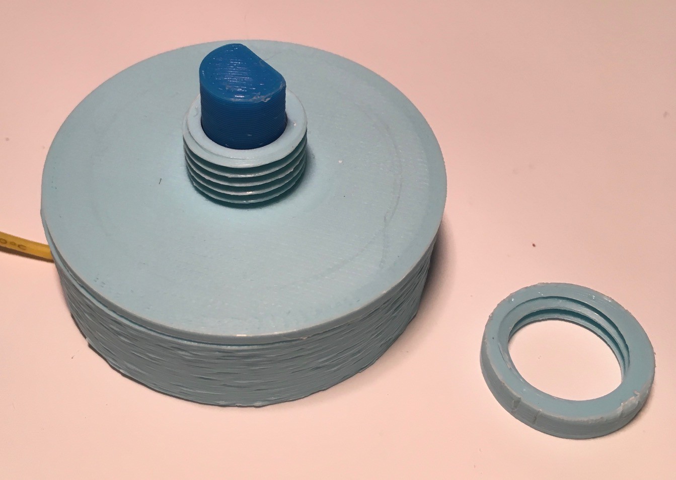
It's not a compact as "store bought" at 50 mm in diameter, but it's certainly useable in many situations including mine. Like a potentiometer, you can read the five different stops with a single analog pin (which was a requirement for my Think-a-Tron 2020 build as I only a few pins available). As can be seen above, it is panel mount.
Here is everything needed to build one.
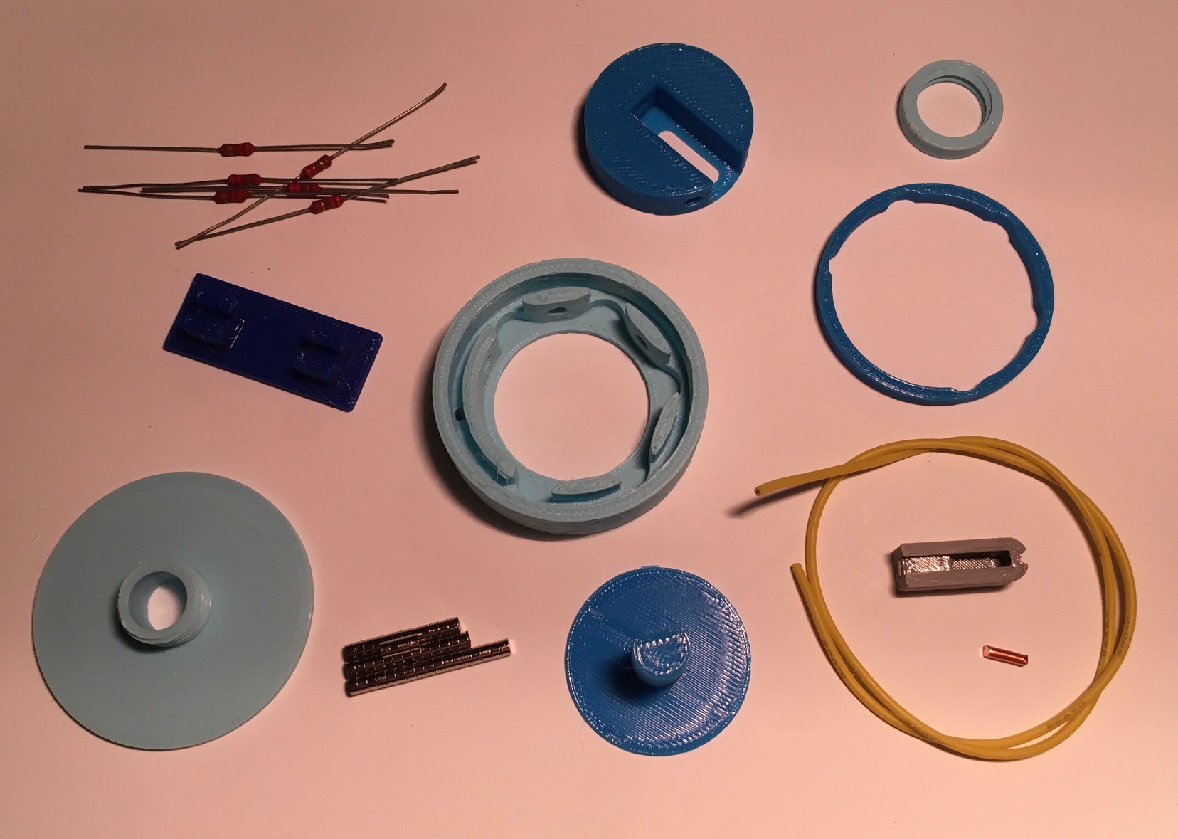
In addition to the printed parts you will need:
- 6 resistors less than 2K in value. Not too important. Mine were 230R.
- Some small disk magnets 3 mm in diameter and 1.7 mm deep.
- A short 7 mm length of 2 mm diameter (12 AWG) uninsulated copper wire.
- Some hookup wire. Mine had soft silicon insulation.
Here is how to put it together.
Step 1 - Prepare the Base
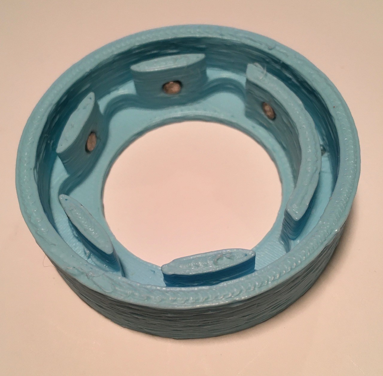
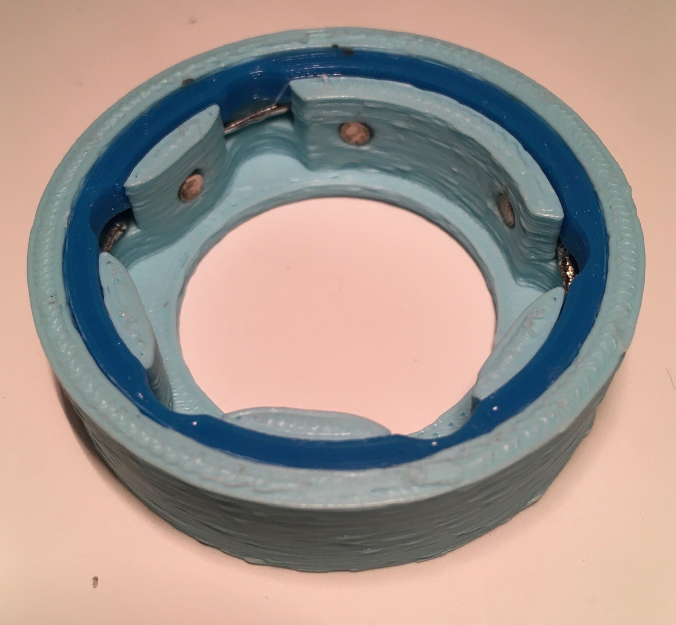
Insert 6 of the magnets into the Base piece. Use a small dab of glue to hold them in place. Make sure that the polarity is the same for all 6 magnets.

Solder the resistors in series as in the above photo. Each should be 15 mm apart.
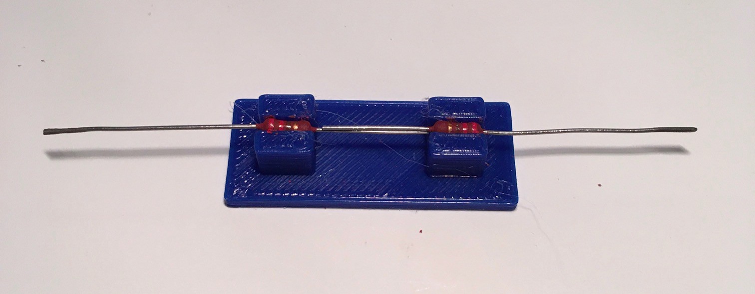
I made a small jig to hold them in place for soldering.
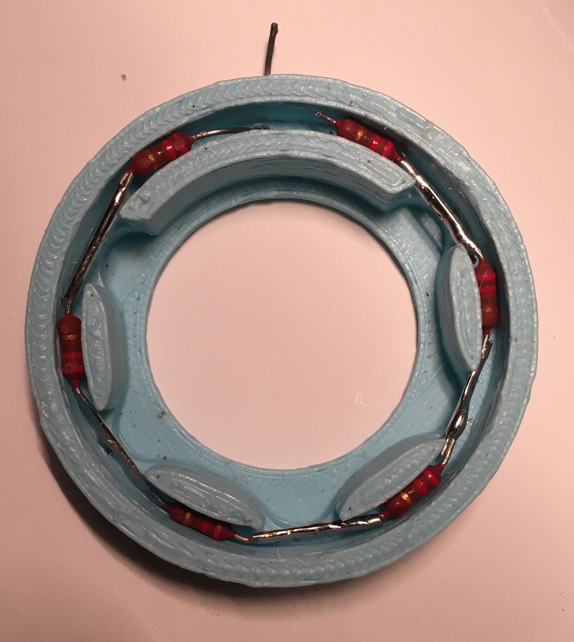
Insert the resistors into the Base channel, behind the "posts" holding the magnets. The resistors go directly behind the posts while the soldered leads go into the "gaps".
When you are satisfied that all the resistors are positioned correctly, push them down to the bottom of the channel, then secure them in place with the "Gasket" piece.
Step 2 - Prepare the Rotor
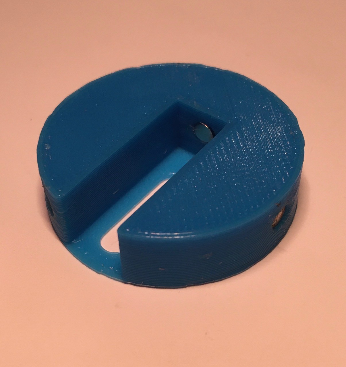
Insert a magnet into each of the three holes on side of the rotor. NOTE: The magnets should be oriented so they attract the magnets that have been set into the inside of the Base.
Insert a stack of three magnets into the hole at the back of the trough pictured above.
Use a little glue to hold all of the magnets in place.
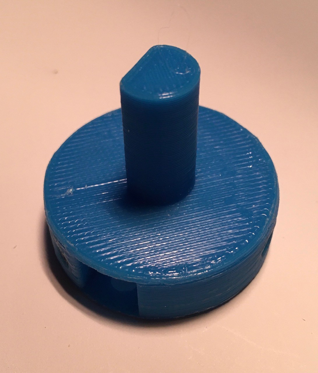
Glue the Rotor Top onto the Rotor so that the trough becomes a small square tunnel. I've aligned the flat edge of the shaft with the left edge of the trough.
Step 3 - Prepare the Piston
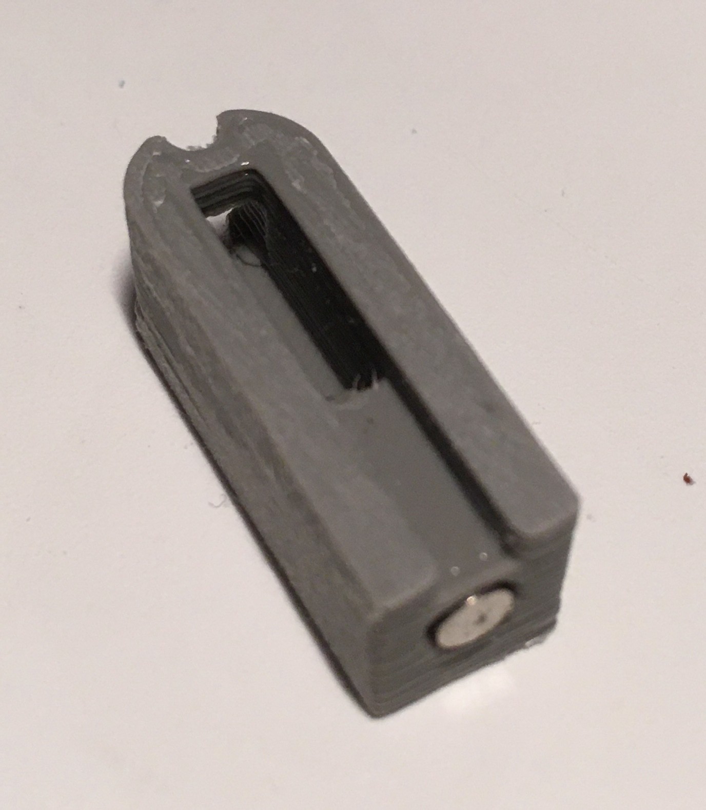
Insert a stack of four magnets into the hole at the "back" of the piston. NOTE: These magnets should be oriented so they repel the magnets that have been set into the inside of the Rotor at the back of the trough. Use a little glue to secure them.
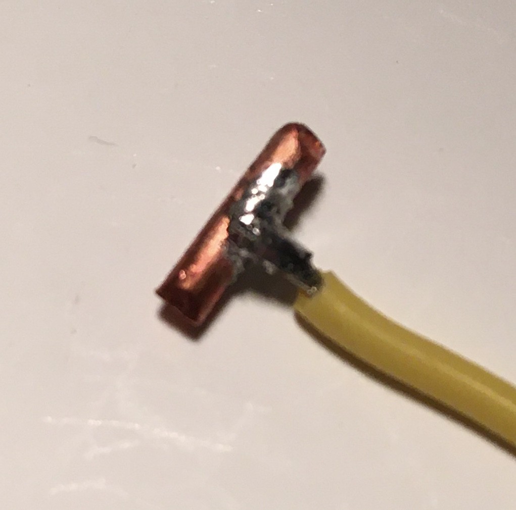
Solder the 7 mm length of 2 mm diameter copper wire to the end of a short length of hookup wire.
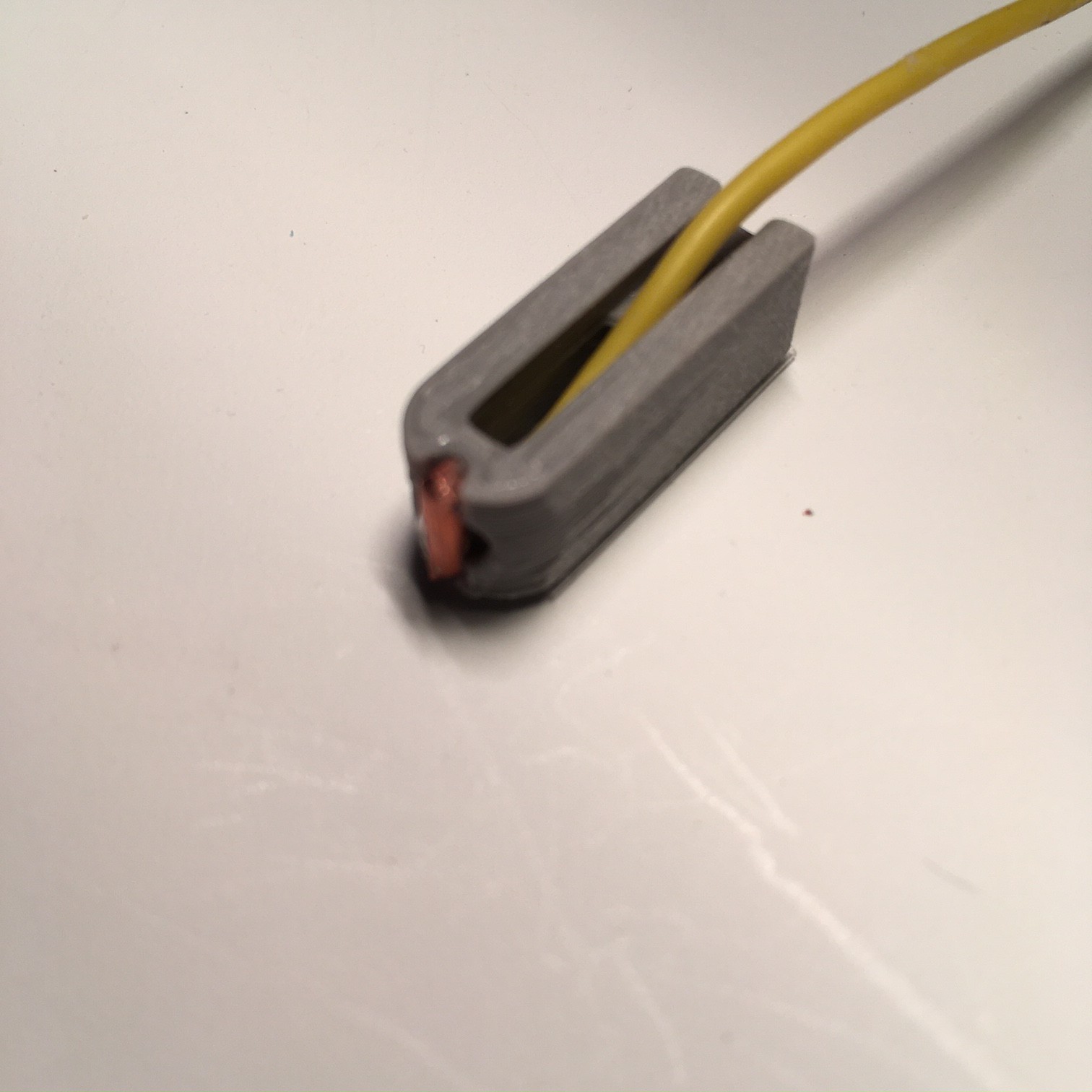
Push the hookup wire through the hole in the front of the Piston and glue the 7 mm copper wire to the groves as in the photo above. Be careful not to get any glue on the front of the copper wire.
Step 4 - Assemble the Rotary Switch
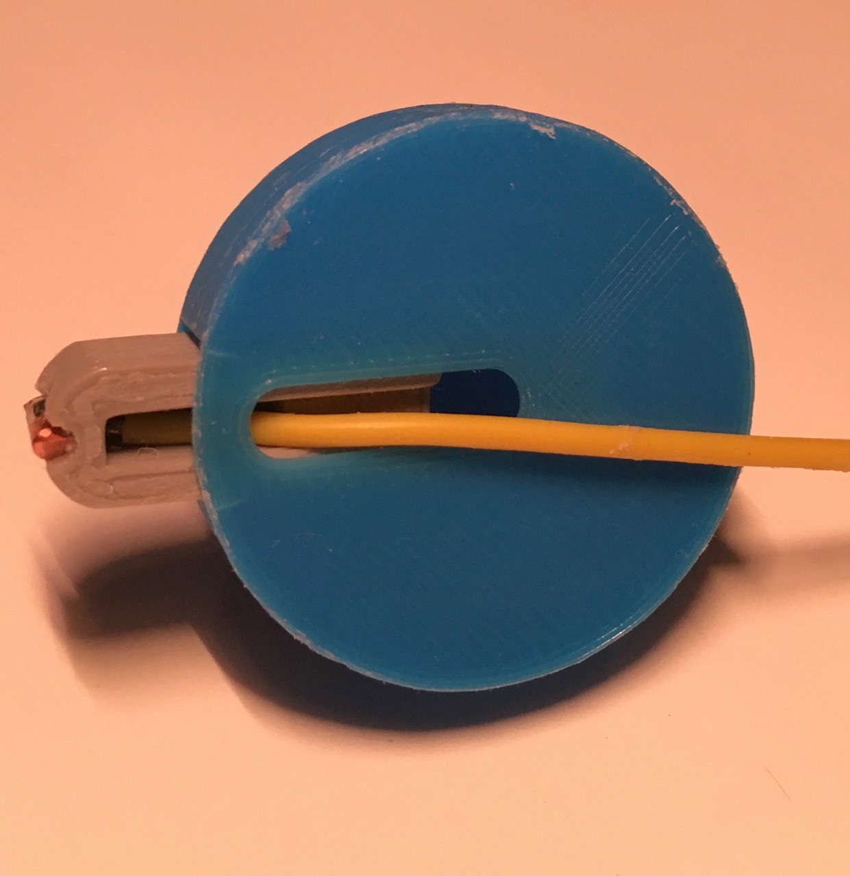
Slide the Piston into the Rotor with the wire pushed through the slot in the bottom as above. The magnets should be pushing the Piston towards the front of the Rotor.
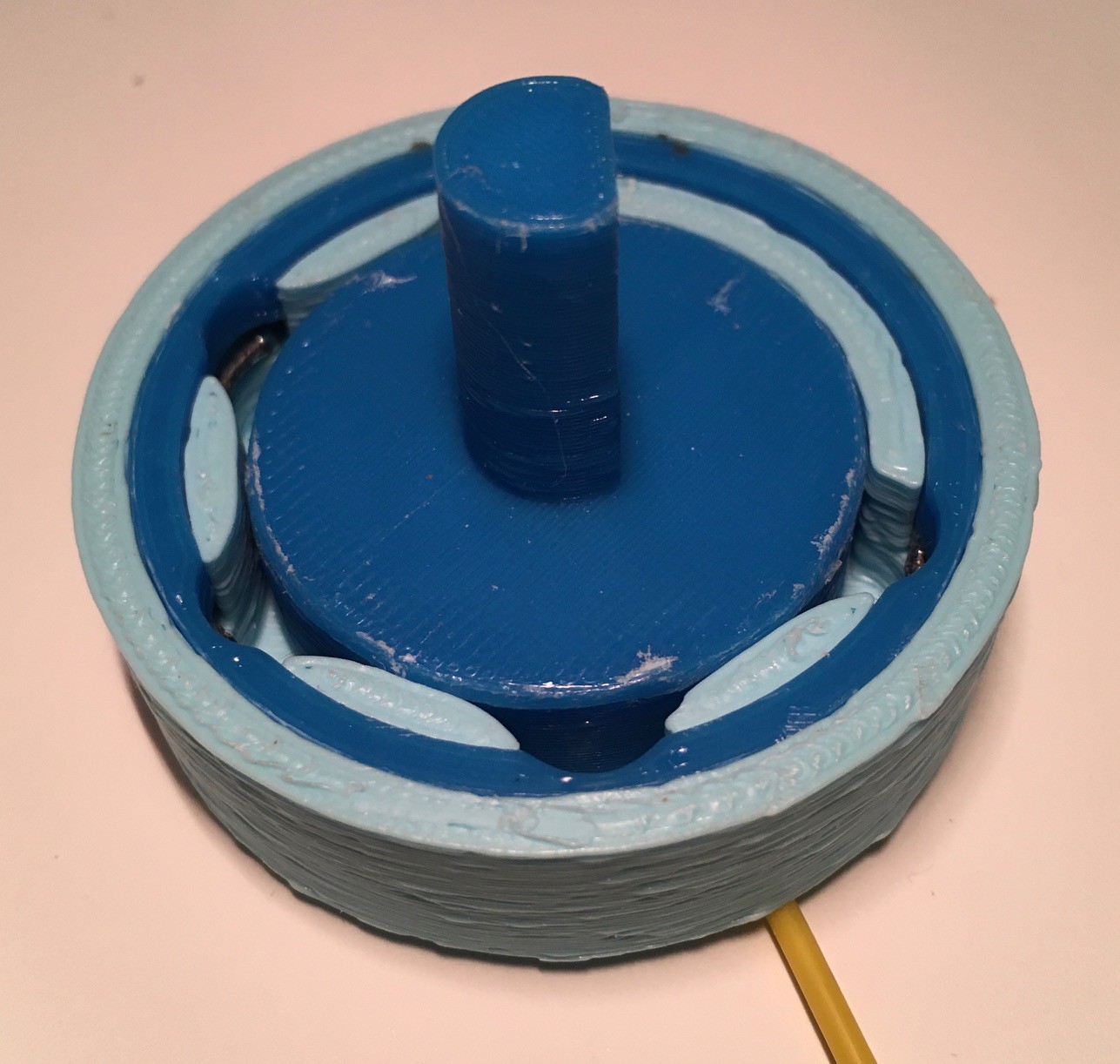
Slot the wire through the hole in the bottom of the Base, push the Piston towards the back of the Rotor trough, and slide the assembly into the Base.
This is a good time to test the switch out. The Rotor should turn freely and the Piston should slide into the Base recesses as you turn. You should feel when the Piston snaps into one of the slots, and feel some resistance when to try to twist away from a slot. That is the detent action that I spoke of.
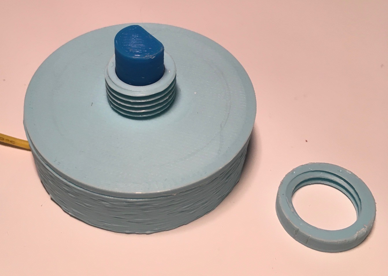
When you are satisfied that everything is working OK, glue the Base Top onto the Base being careful to to gum up the Rotor.
Testing
I wrote a small test sketch to determine the values returned from an analogRead() at each of the five rotary switch positions, and came up with the following values: 233, 196, 159, 115, and 68. Setting a range of -10/+10 around these, the code listed here which has a little averaging to reduce jitter, has no trouble distinguishing between the five positions.
#include "FastLED.h"
#define NUM_LEDS 35
#define LEDS_PIN 6
CRGB leds[NUM_LEDS];int A[35] = {0,0,1,1,1,1,1,
0,1,0,0,1,0,0,
1,0,0,0,1,0,0,
0,1,0,0,1,0,0,
0,0,1,1,1,1,1};int B[35] = {1,1,1,1,1,1,1,
1,0,0,1,0,0,1,
1,0,0,1,0,0,1,
1,0,0,1,0,0,1,
0,1,1,0,1,1,0};int C[35] = {0,1,1,1,1,1,0,
1,0,0,0,0,0,1,
1,0,0,0,0,0,1,
1,0,0,0,0,0,1,
0,1,0,0,0,1,0};int T[35] = {1,0,0,0,0,0,0,
1,0,0,0,0,0,0,
1,1,1,1,1,1,1,
1,0,0,0,0,0,0,
1,0,0,0,0,0,0};int F[35] = {1,1,1,1,1,1,1,
1,0,0,1,0,0,0,
1,0,0,1,0,0,0,
1,0,0,1,0,0,0,
1,0,0,0,0,0,0};int a = 0;
void setup() {
Serial.begin(115200);
Serial.println("Test Resistor Network");
pinMode(A5, INPUT_PULLUP);FastLED.addLeds<NEOPIXEL, LEDS_PIN>(leds, NUM_LEDS);
Serial.begin(115200);
Serial.println("5x7 LED Array");
FastLED.setBrightness(32);
}int countA = 0;
int countB = 0;
int countC = 0;
int countT = 0;
int countF = 0;void loop() {
a = analogRead(5);
Serial.println(a);if (a <= 78 && a >= 58) countF++;
if (a <= 125 && a >= 105) countT++;
if (a <= 169 && a >= 149) countC++;
if (a <= 206 && a >= 186) countB++;
if (a <= 243 && a >= 223) countA++;if (countF > 10) {showLetter(F); countA = 0; countB = 0; countC = 0; countT = 0; countF = 0;}
if (countT > 10) {showLetter(T); countA = 0; countB = 0; countC = 0; countT = 0; countF = 0;}
if (countC > 10) {showLetter(C); countA = 0; countB = 0; countC = 0; countT = 0; countF = 0;}
if (countB > 10) {showLetter(B); countA = 0; countB = 0; countC = 0; countT = 0; countF = 0;}
if (countA > 10) {showLetter(A); countA = 0; countB = 0; countC = 0; countT = 0; countF = 0;}
delay(10);
}void showLetter(int letter[]) {
for (int i = 0; i < NUM_LEDS; i++) {
if (letter[i] == 1) {
leds[i] = CRGB::White;
} else {
leds[i] = CRGB::Black;
}
}
FastLED.show();
}
I printed a small panel to mount the switch on. This is the intended use for the Rotary Switch, to accept a user's answer to a multiple choice question (A, B, C), or a True/False question (T, F).
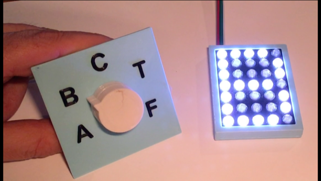
Then I connected a to my 5x7 LED display for a small integration test.
So Why Is This Log Labeled (Part 1)?
This is Part 1 because while I was working on this rotary switch I thought of another scheme that I like better. So I may not end up using this control in Think-a-Tron 2020. This will depend on how my other idea pans out. Stay tuned for Part 2.
 Michael Gardi
Discussions
Become a Hackaday.io Member
Create an account to leave a comment. Already have an account? Log In.