With all of the little bits sorted, I just finished the first major subassembly for Think-a-Tron 2020, the Player Console.
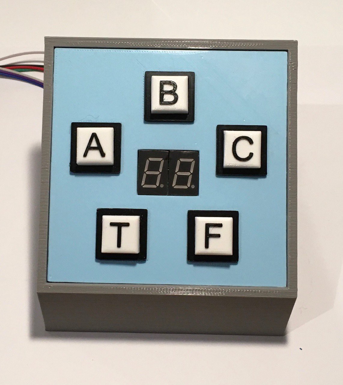
You'll notice something new in the picture above. A two digit seven-segment display that will be used to keep track of the player's score. I made five of the NeoPixel push button switches I talked about in my last log entry. The only change I made was to incorporate the switch leads into my header jack.
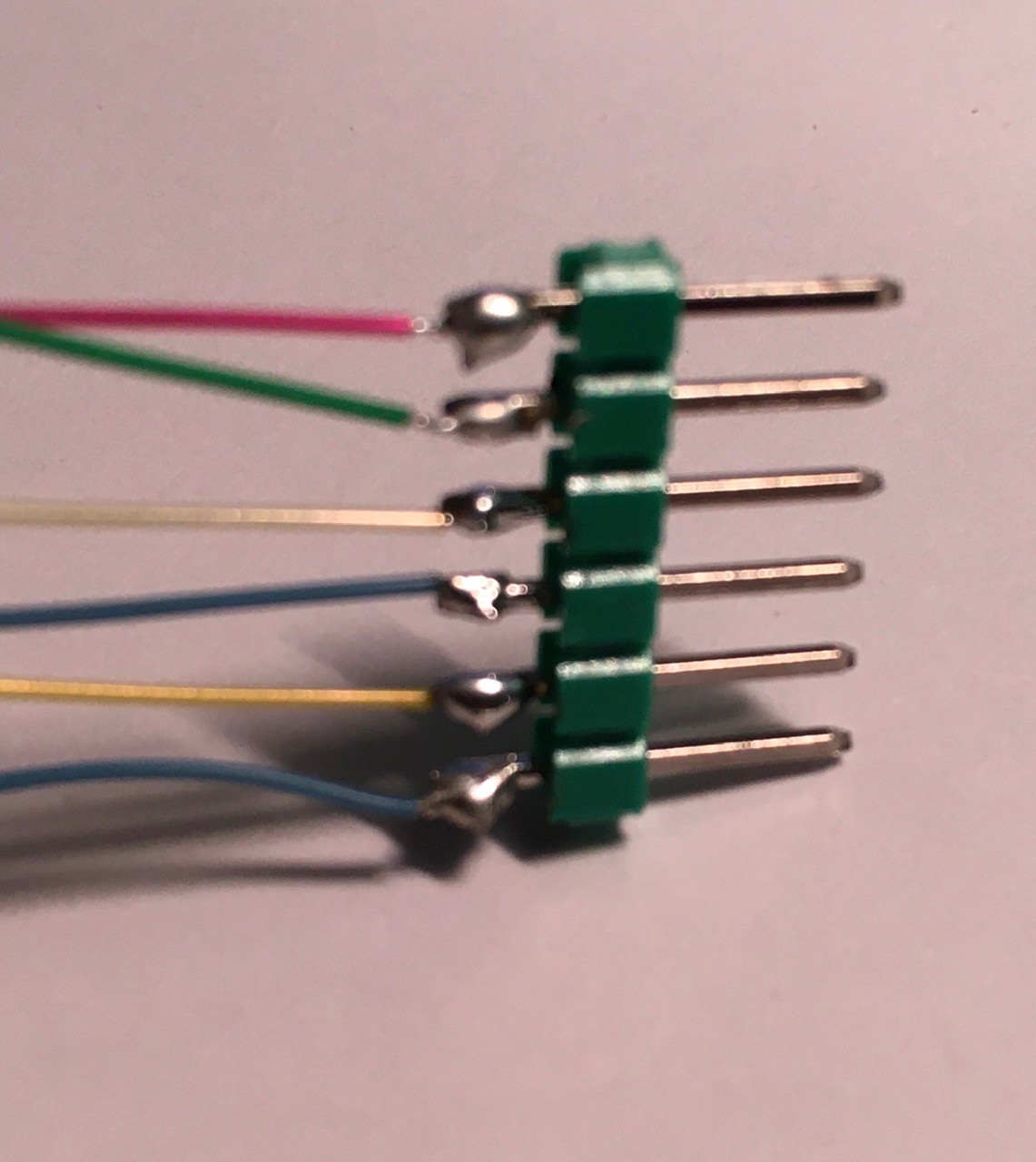
So from top to bottom we have:
- +5V
- Led In
- Led Out
- GND
- Switch Common
- Switch NO
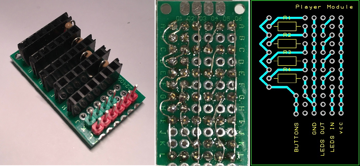
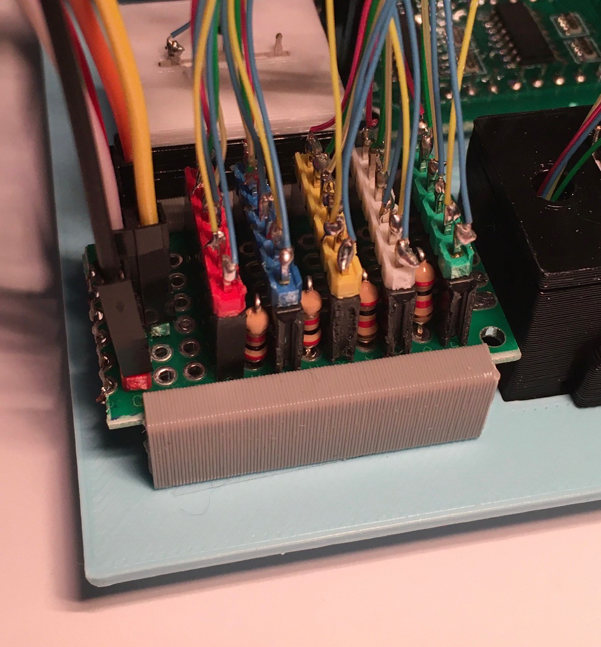
I used a perf board with headers to help sort out the wiring. This Player Module also has the four 2K resistors used to determine which button is pressed. Point-to-point wiring was tight but doable. If I could get PCBs cheaply (it's the shipping to Canada that kills me), I would have gone that route.
I created a small slotted clamp to hold the Player Module perf board and attached it with two sided tape (or glue) to the back of a panel that I printed to mount the switches and display.
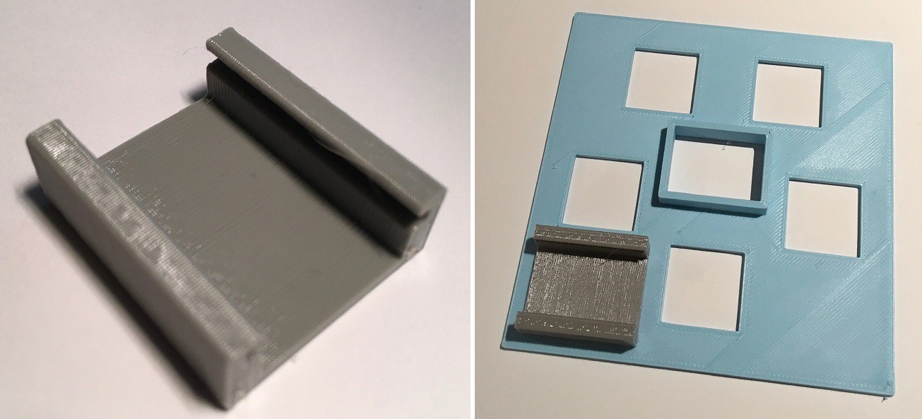
I added headers to the back of the seven-segment display (a Robojax Whmxe 595-2 74HC595 Driving 2 Digit 0.5in Seven Segment Display for Arduino - from Amazon) and mounted the display in the center rectangle with the raised edges. The front of the display should end up being flush with the front face of the panel. The switches are pushed in from the front of the panel and held in place with the tabs you can see in the second picture below.
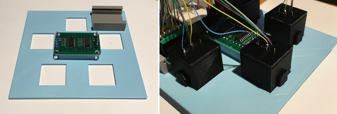
I slid the perf board into the holder and began plugging in the switches.
Then I wired the Player Console to an Arduino Nano for a test.
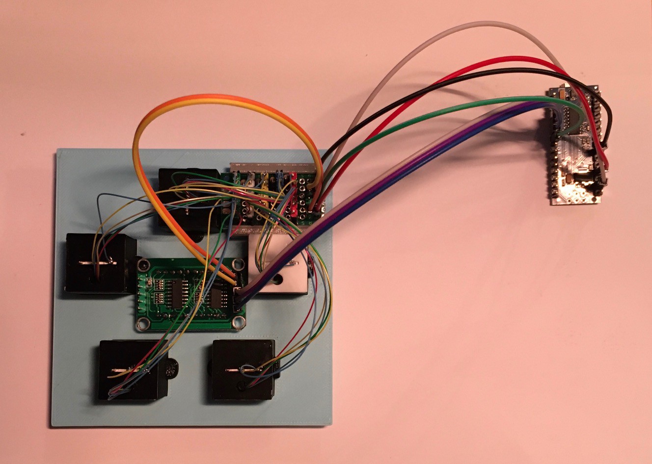
Connect:
| From | To |
|---|---|
| Player Module VCC | Arduino +5V |
| Player Module LEDS In | Arduino D6 |
| Player Module GND | Arduino GND |
| SS Display VCC | Player Module VCC (Second Header) |
| SS Display GND | Player Module GND (Second Header) |
| SS Display SDI | Arduino D9 |
| SS Display SCLK | Arduino D8 |
| SS Display LOAD | Arduino D7 |
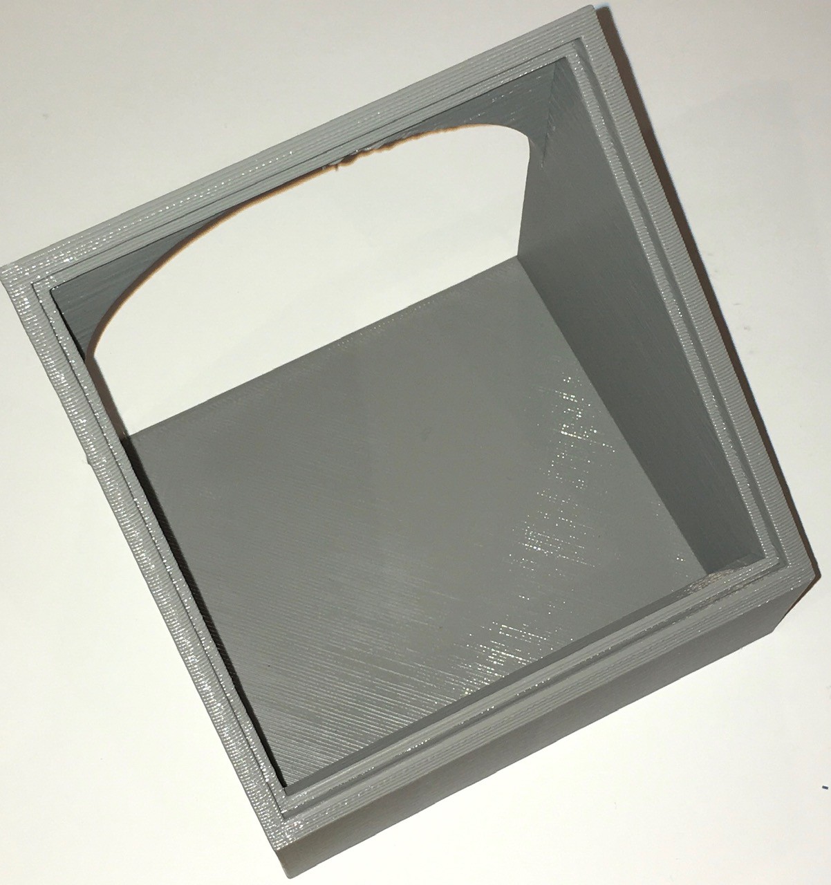
With everything attached mount the Player Panel onto the printed console seen below.
And the final result can be seen below running a small test sketch. The buttons are programmed to light when pressed and act as radio buttons so the only the last button pressed is illuminated. The counter was programmed to increment on each button press.
#include "FastLED.h"
#include <ShiftRegister74HC595.h>

#define SDI 9
#define SCLK 8
#define LOAD 7
#define DIGITS 2

// create shift register object (number of shift registers, data pin, clock pin, latch pin)
ShiftRegister74HC595 sr (DIGITS, SDI, SCLK, LOAD);


int value,digit1,digit2,digit3,digit4;
uint8_t  digits[] = {B11000000, //0
                      B11111001, //1
                      B10100100, //2
                      B10110000, //3
                      B10011001, //4
                      B10010010, //5
                      B10000010, //6
                      B11111000, //7
                      B10000000, //8
                      B10010000 //9
                     };

#define NUM_LEDS 5
#define LEDS_PIN 6
CRGB leds[NUM_LEDS];

int buttons = 0;

int A = 0;
int B = 1;
int C = 2;
int T = 3;
int F = 4;

int countA = 0;
int countB = 0;
int countC = 0;
int countT = 0;
int countF = 0;

int score = 0;

void setup() {
  Serial.begin(115200);
  Serial.println("Single LED");
  pinMode(A5, INPUT_PULLUP);

  FastLED.addLeds<NEOPIXEL, LEDS_PIN>(leds, NUM_LEDS);
  clearAnswers();
  FastLED.show();
}

void loop() {
  buttons = analogRead(5);
  Serial.println(buttons);

  if (buttons <= 24 && buttons >= 04) countA++;
  if (buttons <= 86 && buttons >= 66) countB++;
  if (buttons <= 134 && buttons >= 114) countC++;
  if (buttons <= 177 && buttons >= 157) countT++;
  if (buttons <= 215 && buttons >= 195) countF++;

  if (countA > 3) {showAnswer(A); FastLED.show(); waitForButtonUp(); score++; countA = 0; countB = 0; countC = 0; countT = 0; countF = 0;}
  if (countB > 3) {showAnswer(B); FastLED.show(); waitForButtonUp(); score++; countA = 0; countB = 0; countC = 0; countT = 0; countF = 0;}
  if (countC > 3) {showAnswer(C); FastLED.show(); waitForButtonUp(); score++; countA = 0; countB = 0; countC = 0; countT = 0; countF = 0;}
  if (countT > 3) {showAnswer(T); FastLED.show(); waitForButtonUp(); score++; countA = 0; countB = 0; countC = 0; countT = 0; countF = 0;}
  if (countF > 3) {showAnswer(F); FastLED.show(); waitForButtonUp(); score++; countA = 0; countB = 0; countC = 0; countT = 0; countF = 0;}

  showScore(score, 0);

  delay(20);
}

void waitForButtonUp() {
  while (analogRead(5) < 300) {
    delay(50);
  }
}

void clearAnswers() {
  for(int i = 0; i < NUM_LEDS; i++) {
    leds[i] = CRGB::Black;
  }
}

void showAnswer(int answer) {
  clearAnswers();
  leds[answer] = CRGB::White;
}

void showScore(int score1, int score2) {
    digit2=score1 % 10 ;
    digit1=(score1 / 10) % 10 ;
    //Send them to 7 segment displays
    uint8_t numberToPrint[]= {digits[digit2],digits[digit1]};
    sr.setAll(numberToPrint);

    //digit4=score2 % 10 ;
    //digit3=(score2 / 10) % 10 ;
    //Send them to 7 segment displays
    //uint8_t numberToPrint2[]= {digits[digit4],digits[digit3]};
    //sr.setAll(numberToPrint2);
}
Player two will be ready soon.
 Michael Gardi
Discussions
Become a Hackaday.io Member
Create an account to leave a comment. Already have an account? Log In.